 Tweet
Tweet
What Happens to a head in a machine shop
First Not all shops have the same equipment and the procedures from one shop to the next can and will differ.
Some shops cater to domestics and others imports or even diesels.
Some shops will view everything as a �stock� rebuilds.
So�.
The most important thing to know is the shop you use and the equipment they will use.
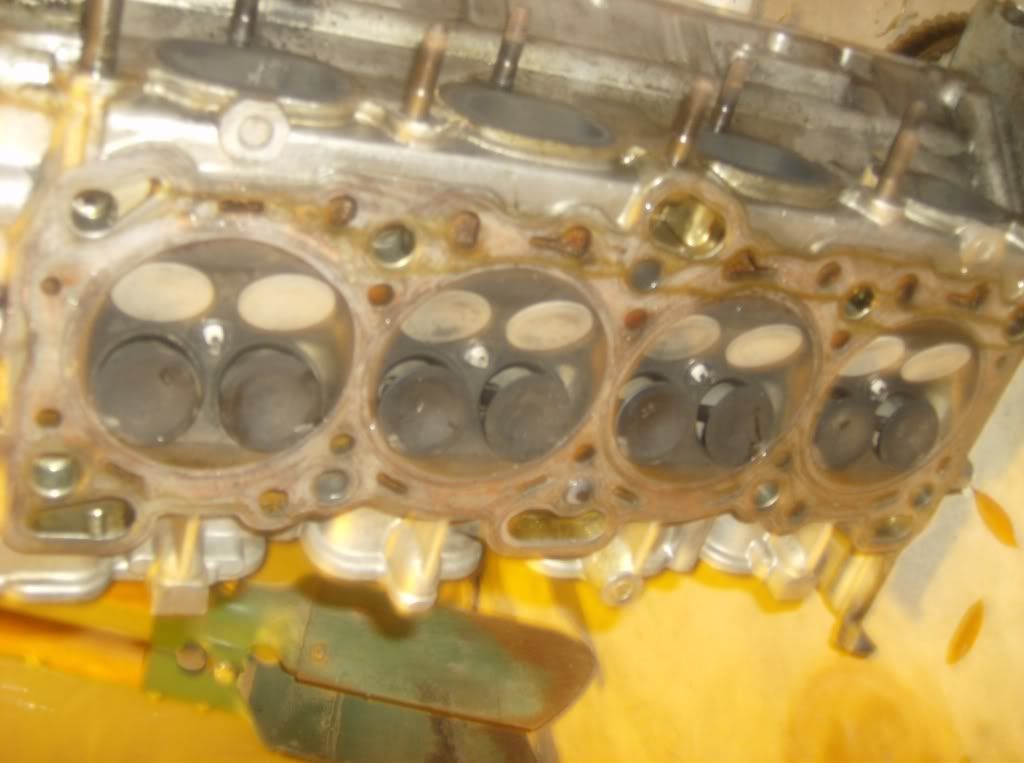
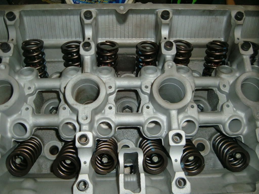
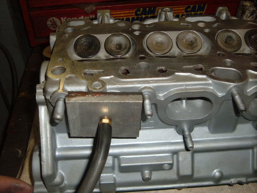
The subject head is a Mitsubishi 4G63 7 Bolt
The first thing that should happen is the machinist looks at the head. Checking for the obvious damage, broken bolts, stripped bolt holes, bent valves, ect.
At this point it is up to you as the customer, inform the shop what you want done, such as�
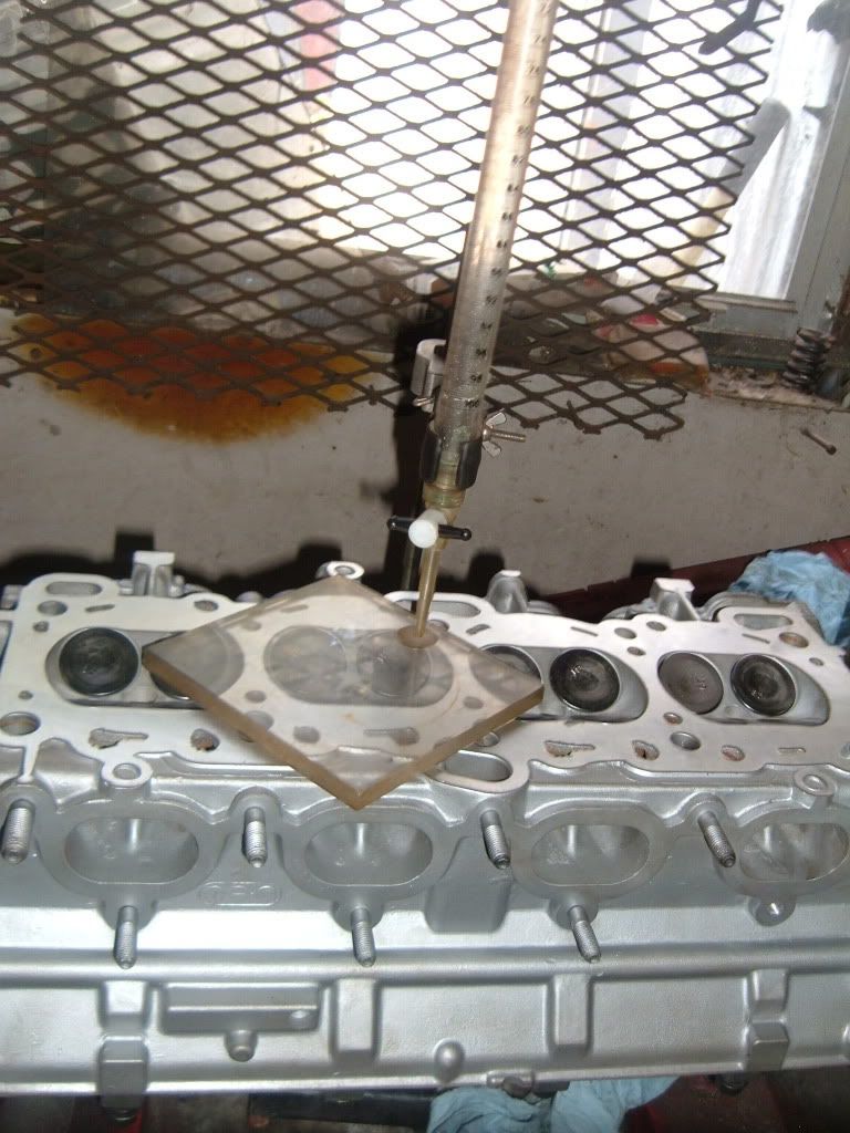
1) Pressure test for cracks
2) Valve job
3) Surface
4) Guide work
5) Any performance work wanted
Also now is the time to speak about who will provide what parts, valves, seals, guides, springs, ect.
Now the shop should be able to give you, the customer, an approximate estimate of what the parts and labor will cost.
You as the customer have the choice to agree, or go somewhere else.
Now that your head is at the machine shop, and you have agreed to have the work done.
The first thing to happen is the head will be disassembled.
The tools needed are
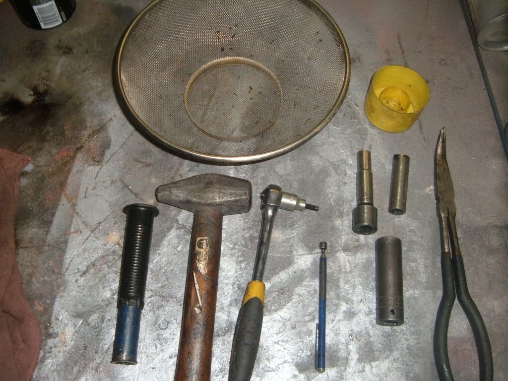
Wire basket for small parts springs, valves, ect
Small container for valve locks
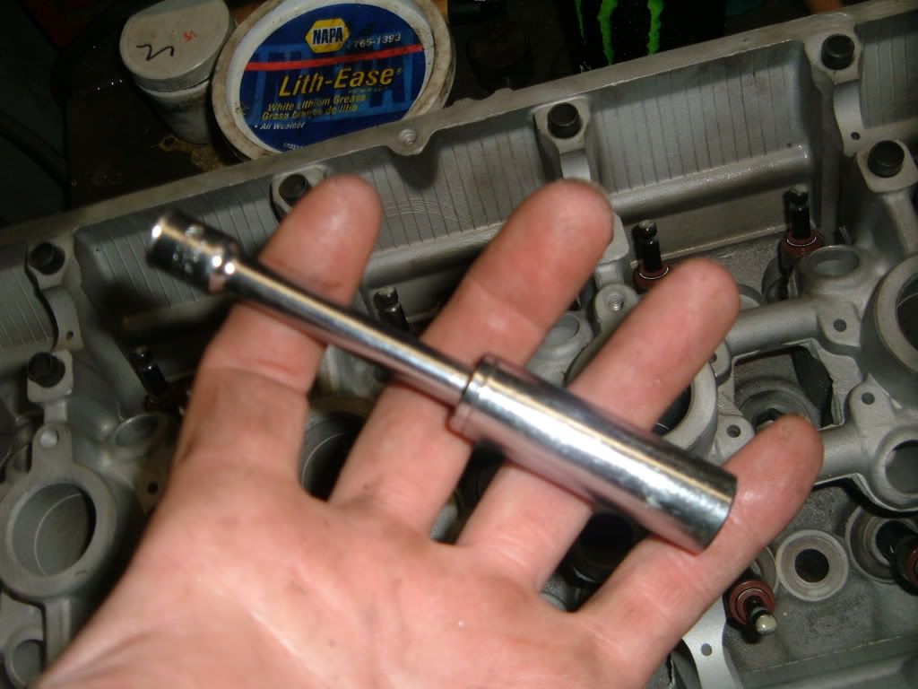
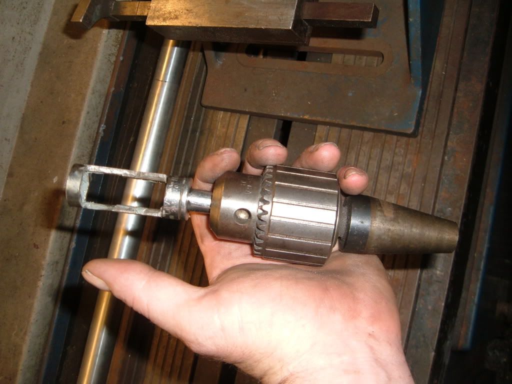
Valve lock release tool (socket method)
Hammer
10mm socket
12mm socket
12mm socket
Ratchet
5.5mm allen bit socket or wrench
Pocket magnet
Long reach needle nose pliers w/45* bend
Impact gun (not pictured)
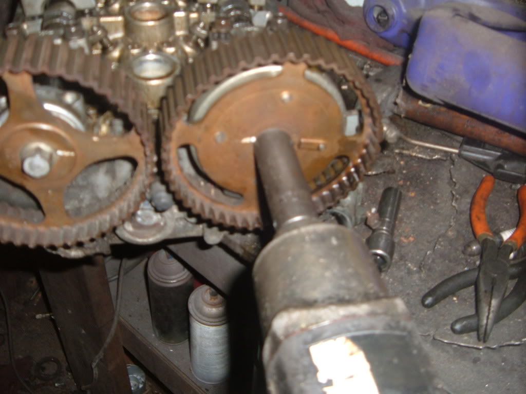
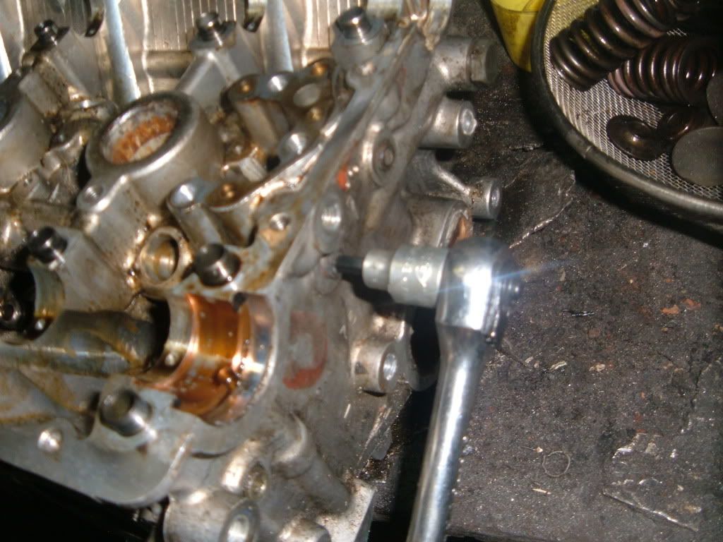
Cam gears come off first, use impact with the 17mm socket
Next remove the cam tower caps, use impact or ratchet w/12mm socket.
Start at the ends working towards the center
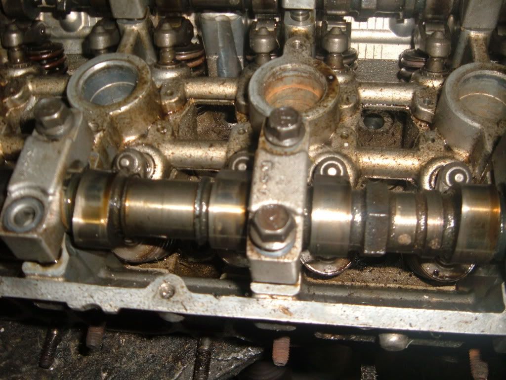
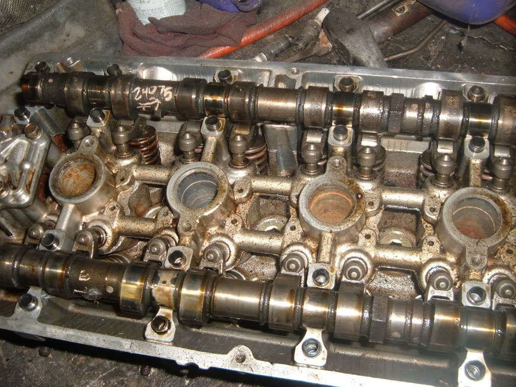
Once the cam caps are removed, lift the cams out.
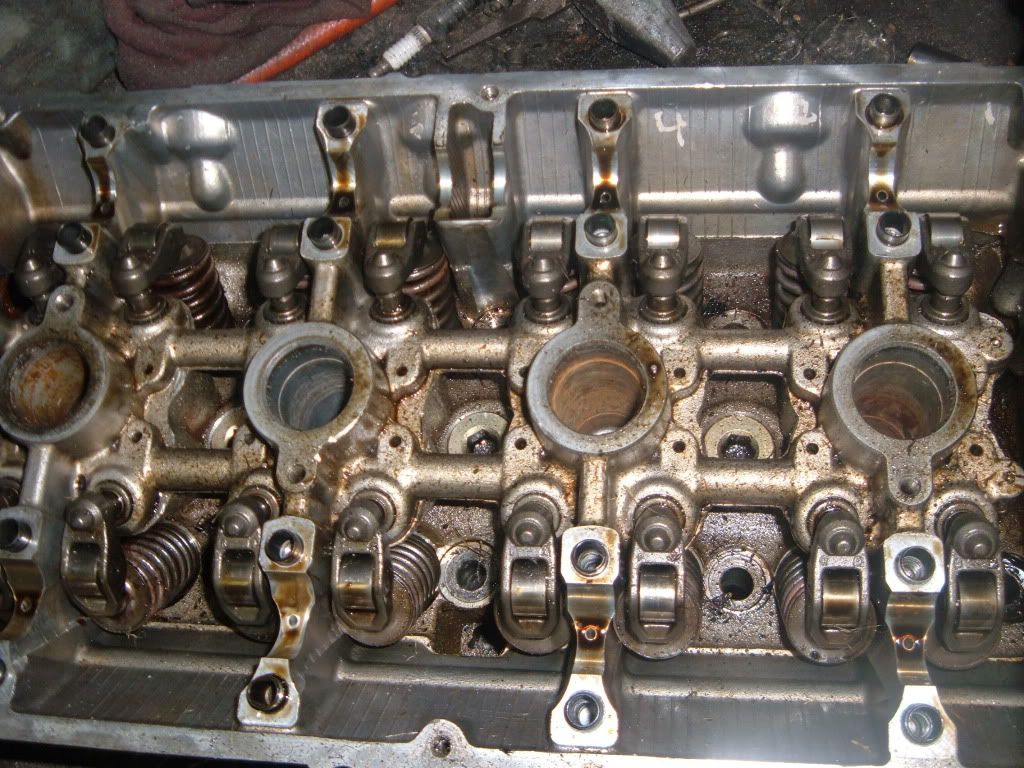
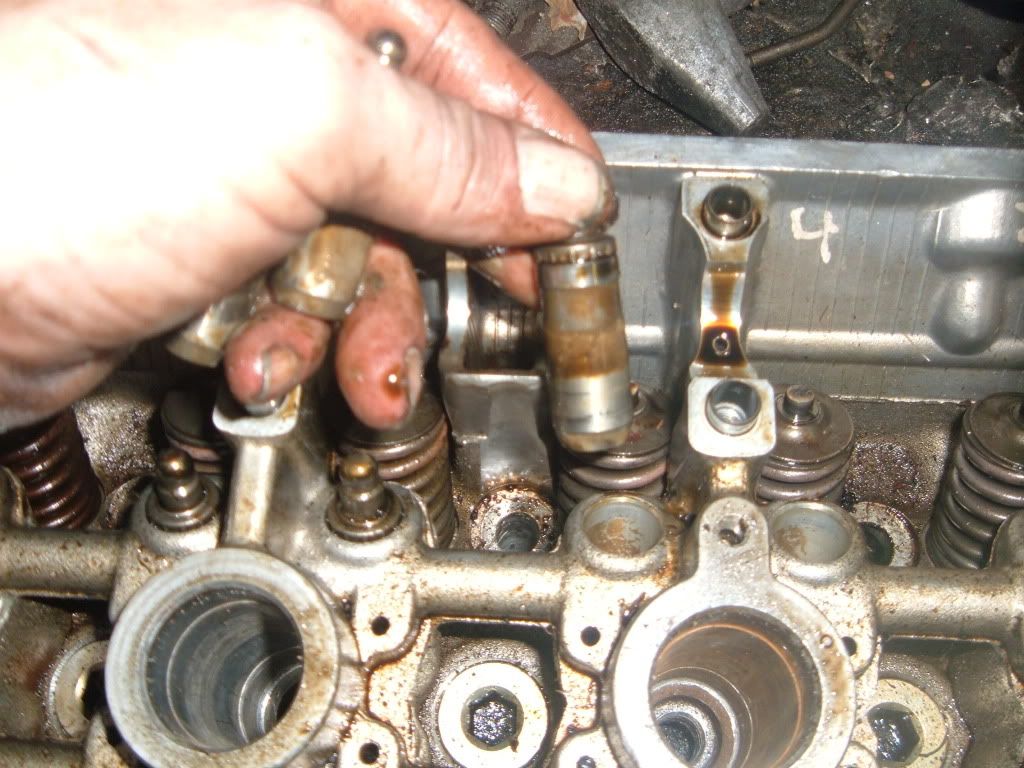
Next lift the roller followers out
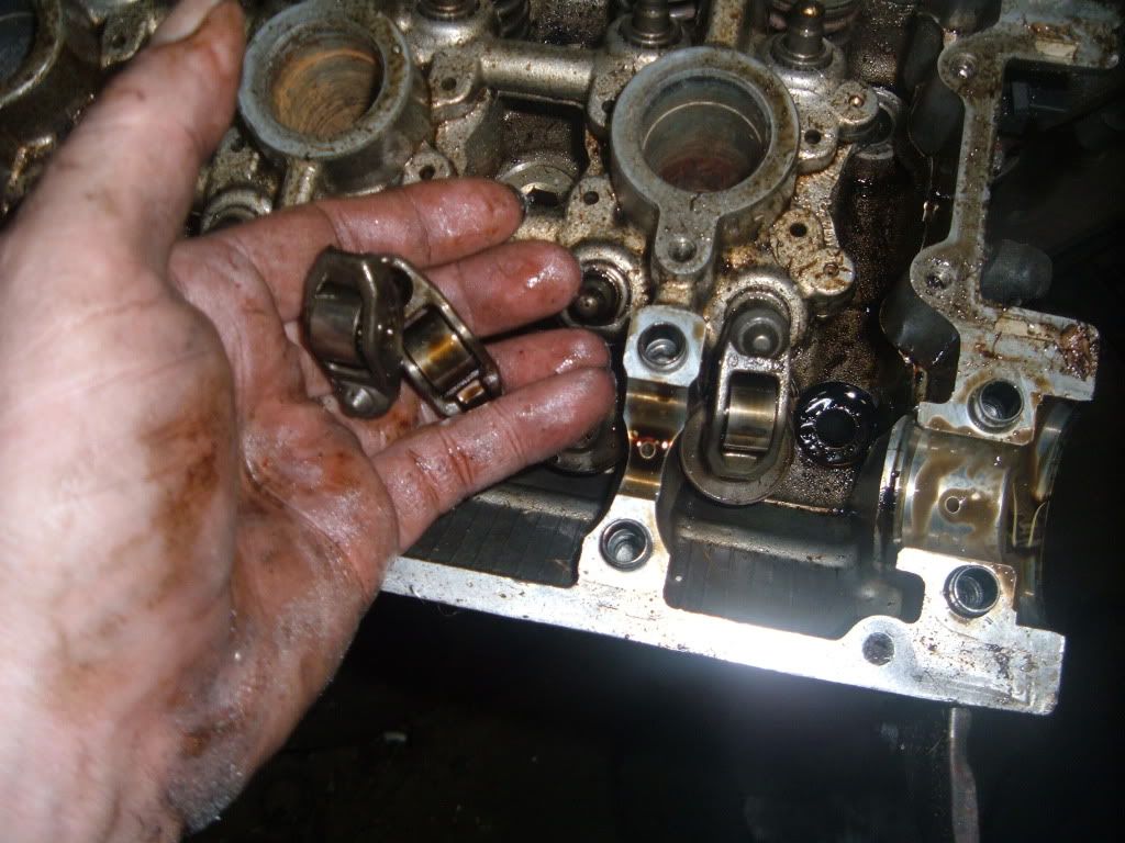
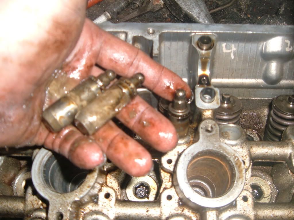
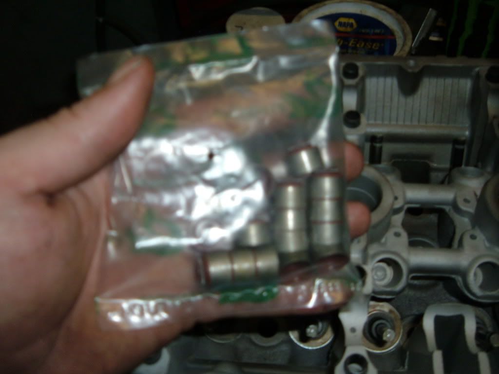
Now you can remove the HLA�s
Now remove the oil spliter
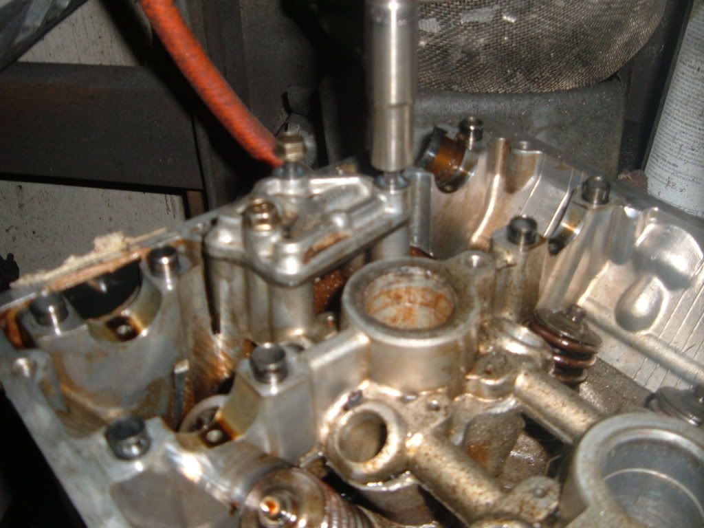
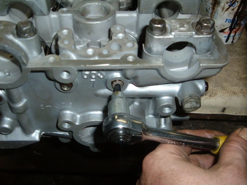
Now remove any other small bolts
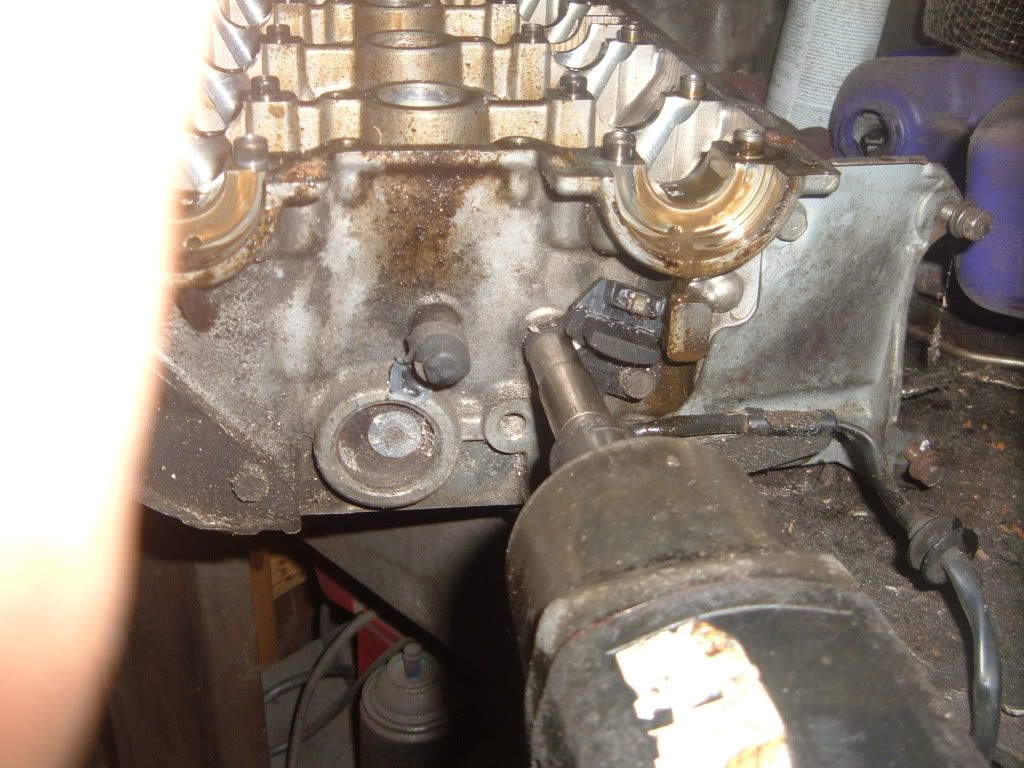
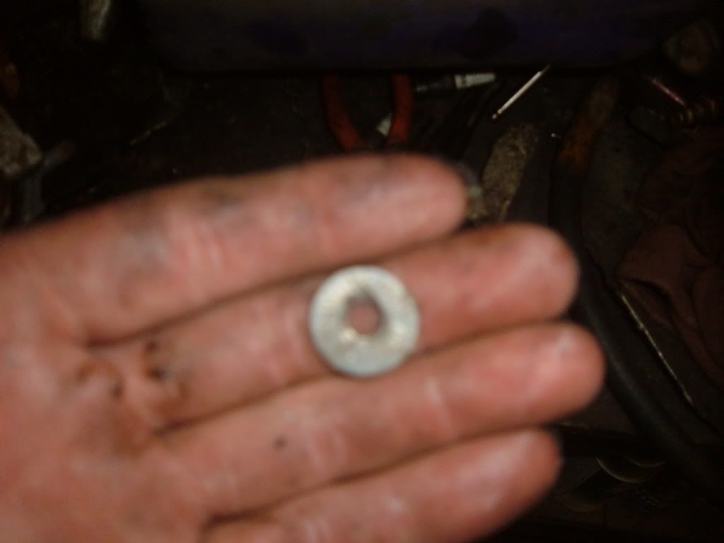
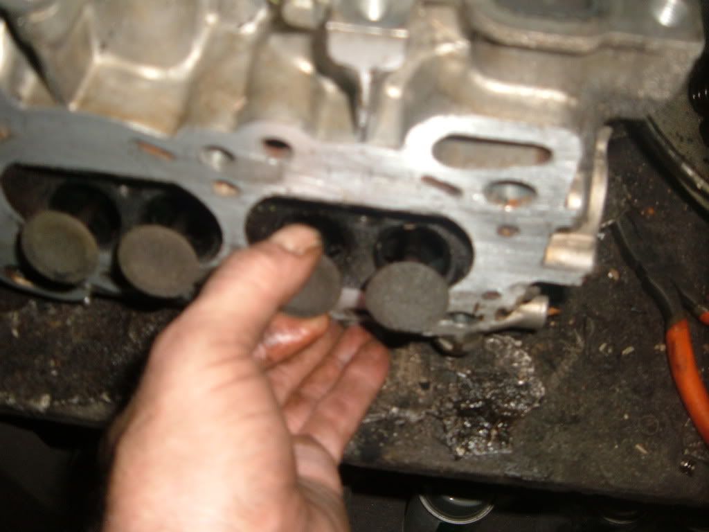
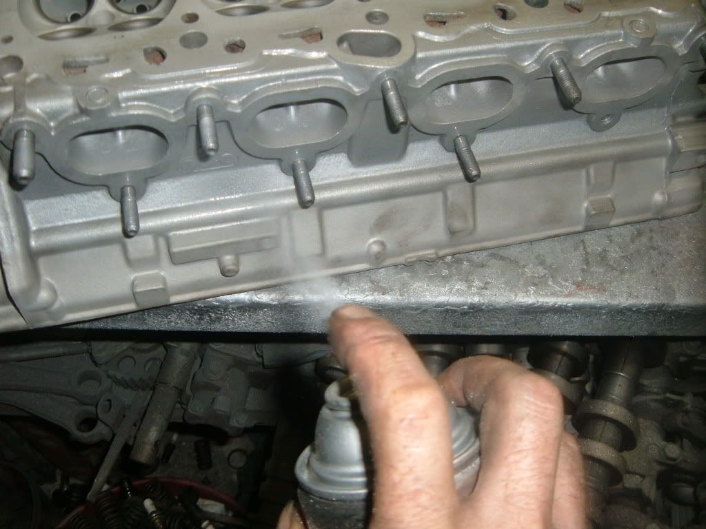
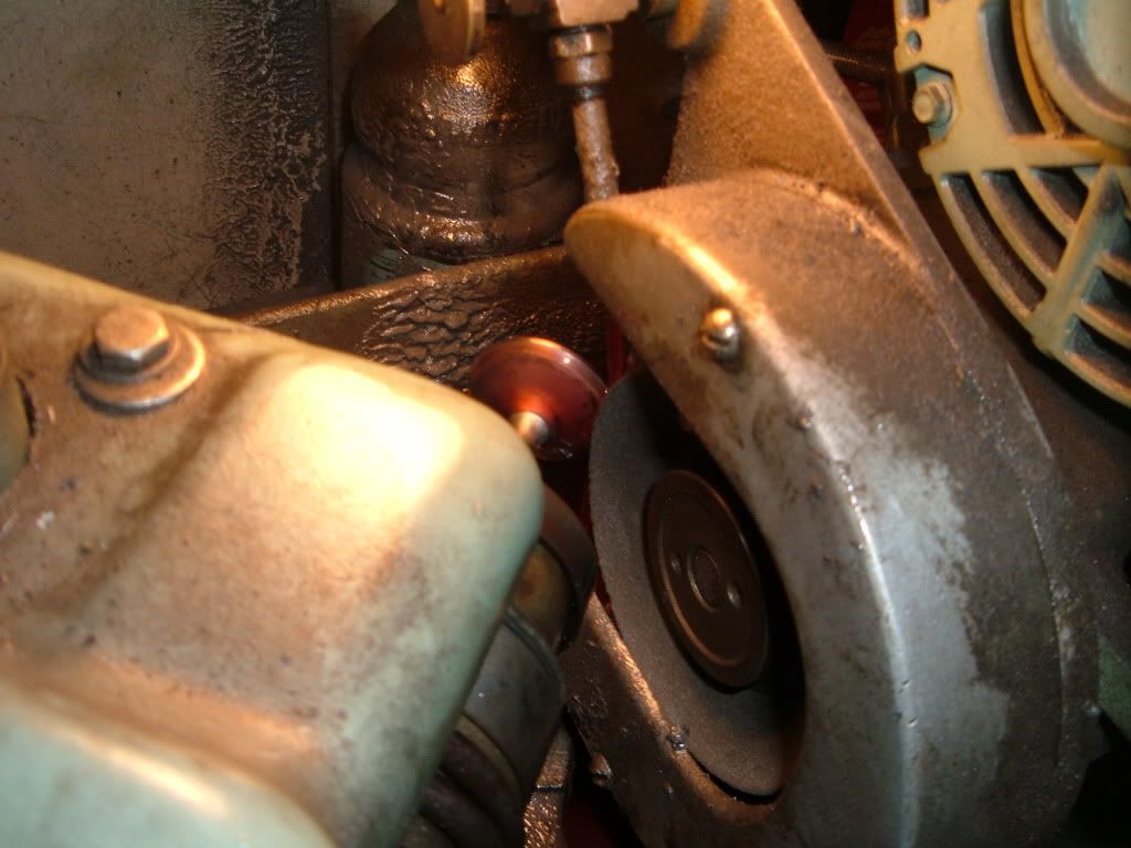
This is a �heat tab� Most machine shops use them.
The center will slide down at 240-250* and totally dissolve at 260*
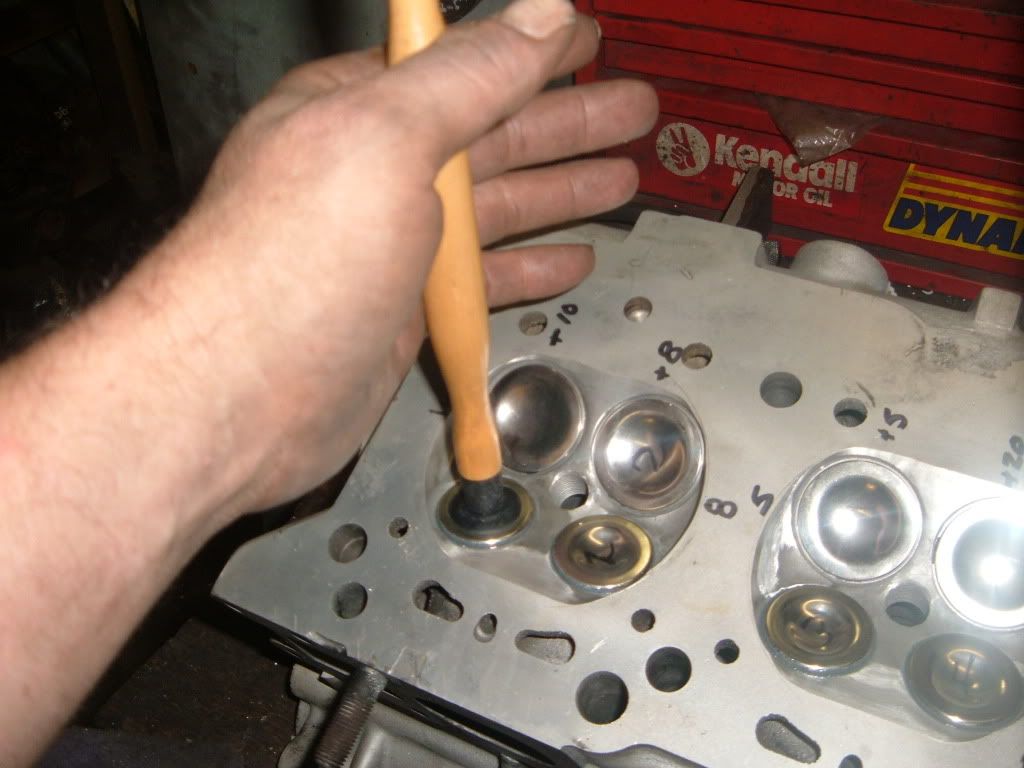
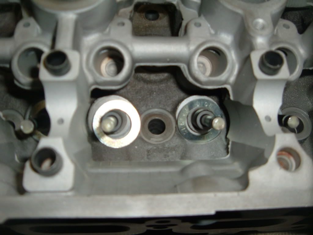
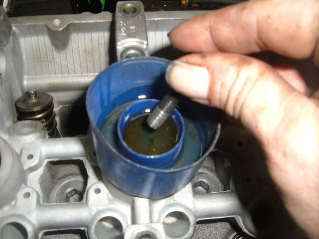
Next is to remove the valve train.
Yes the same method that a lot of DIY people use are used in a machine shop.
Use a basket and a paint cap, have a pocket magnet handy too.
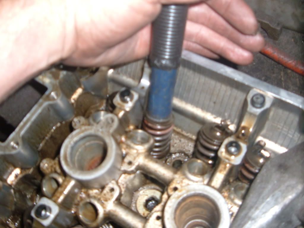
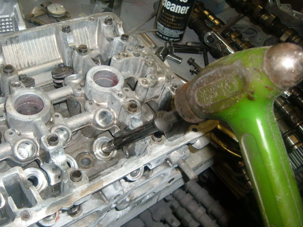
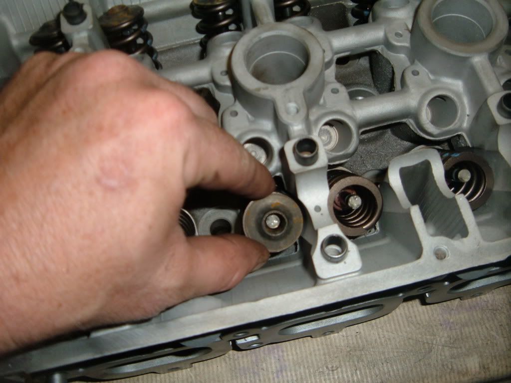
Have your �tool� and hammer ready to go
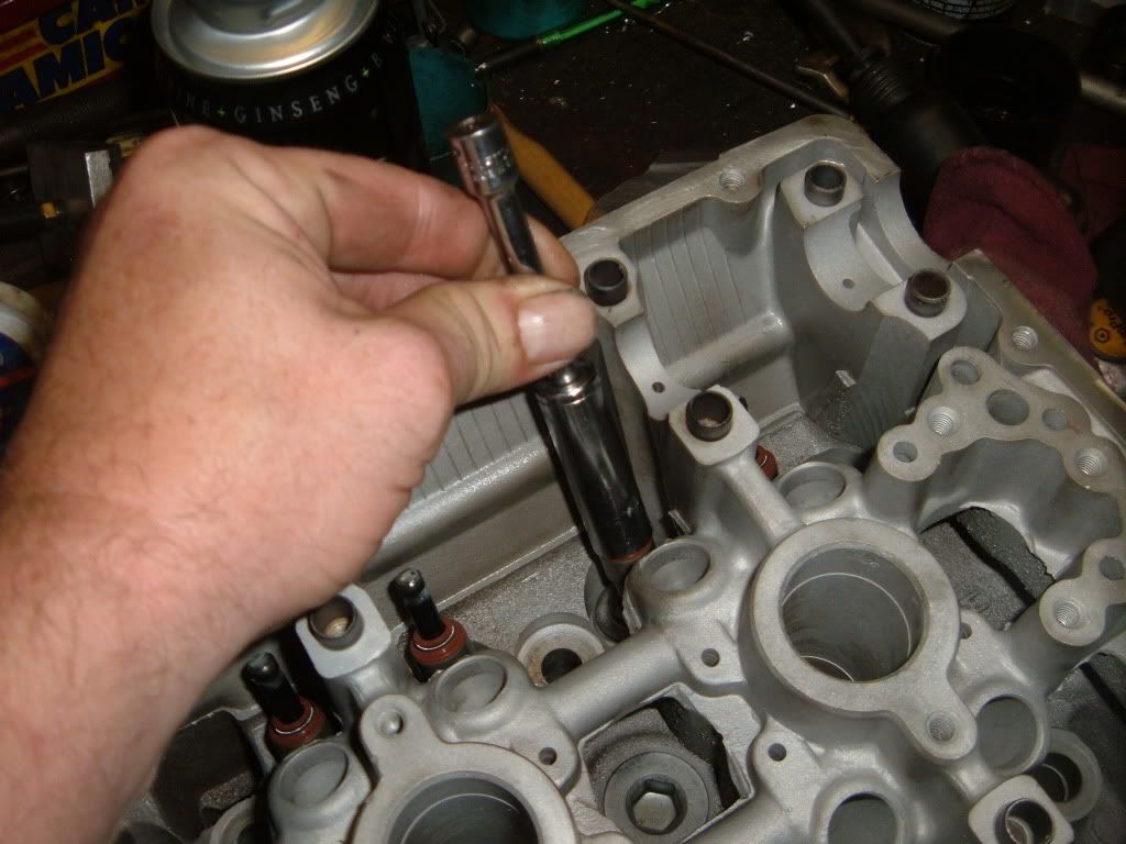
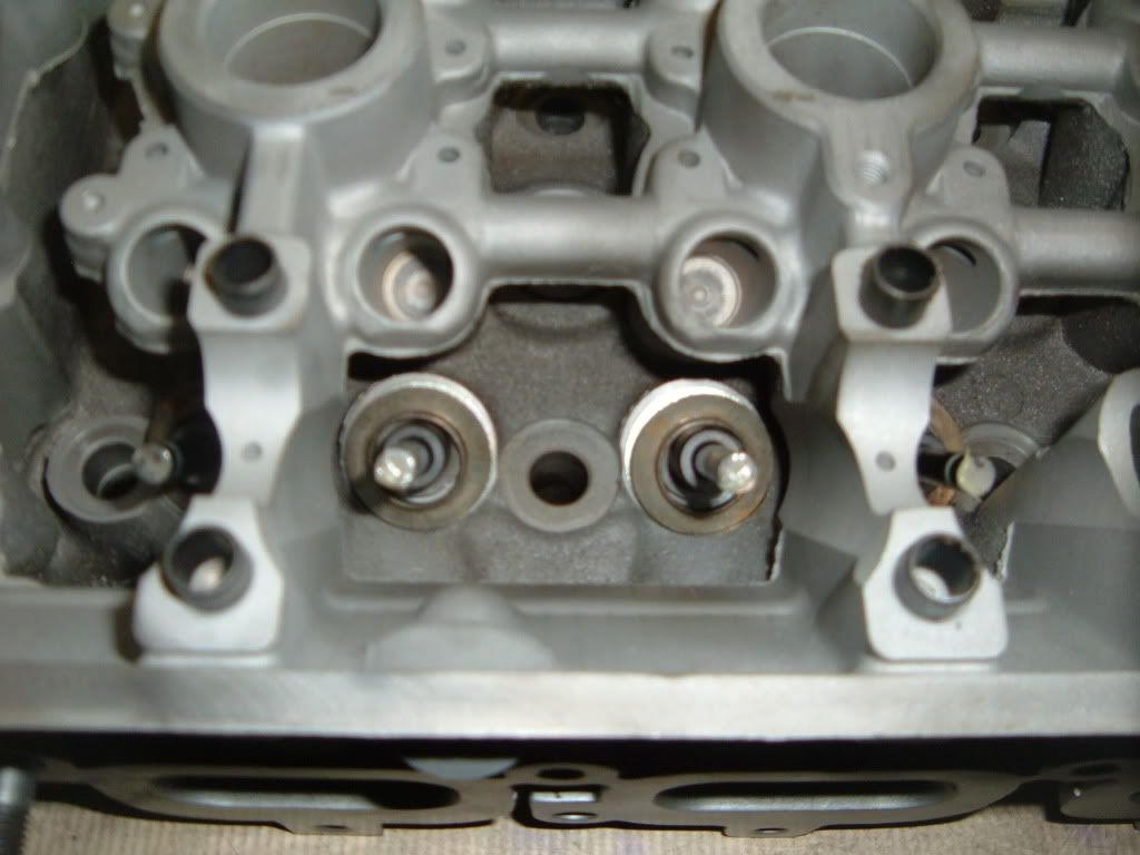
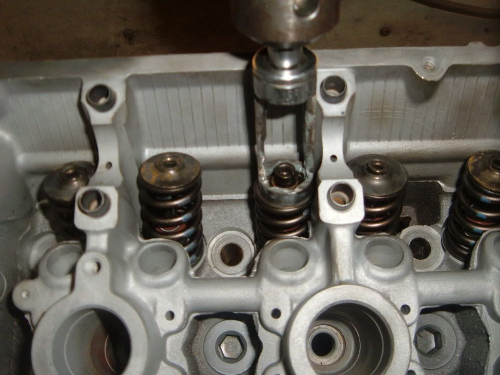
Place the tool on the spring retainer and give it a firm whack.
The locks will stay in the tool and release the retainer and spring.
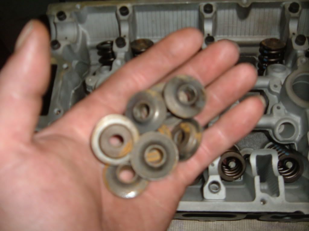
Place the retainers and spring in the basket
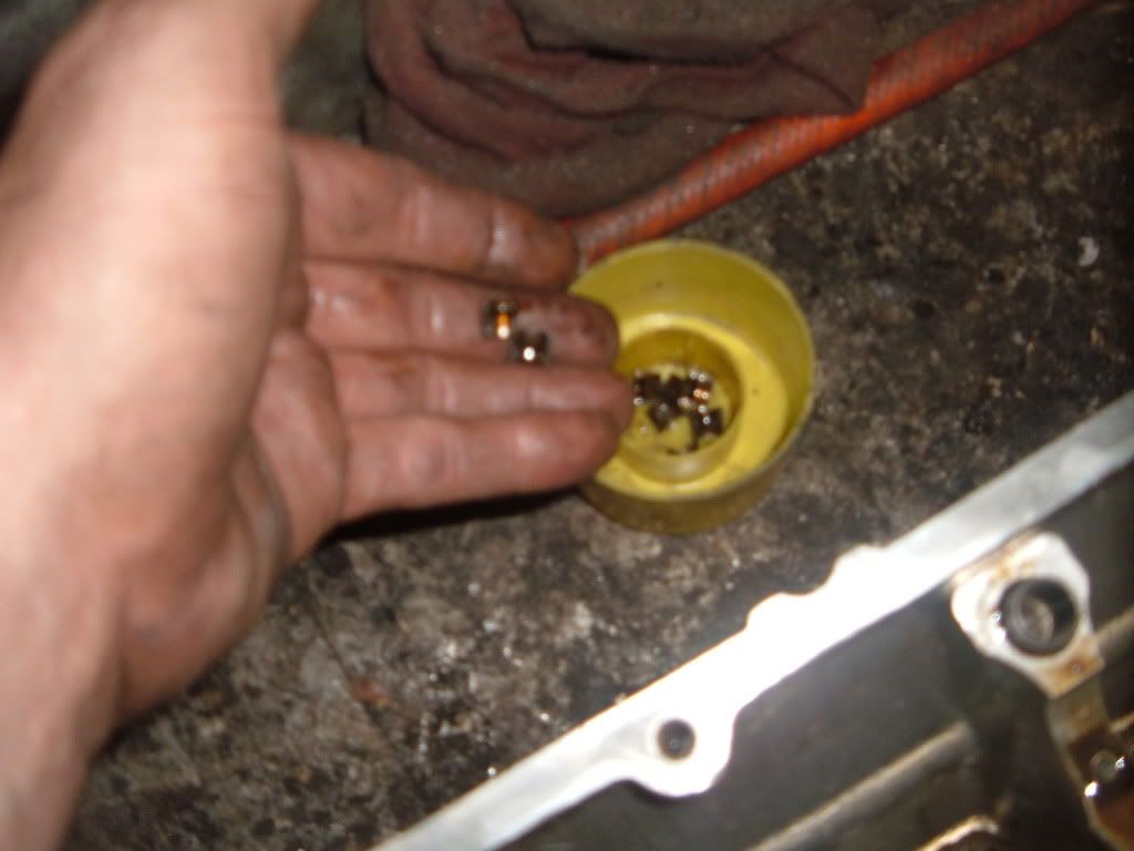
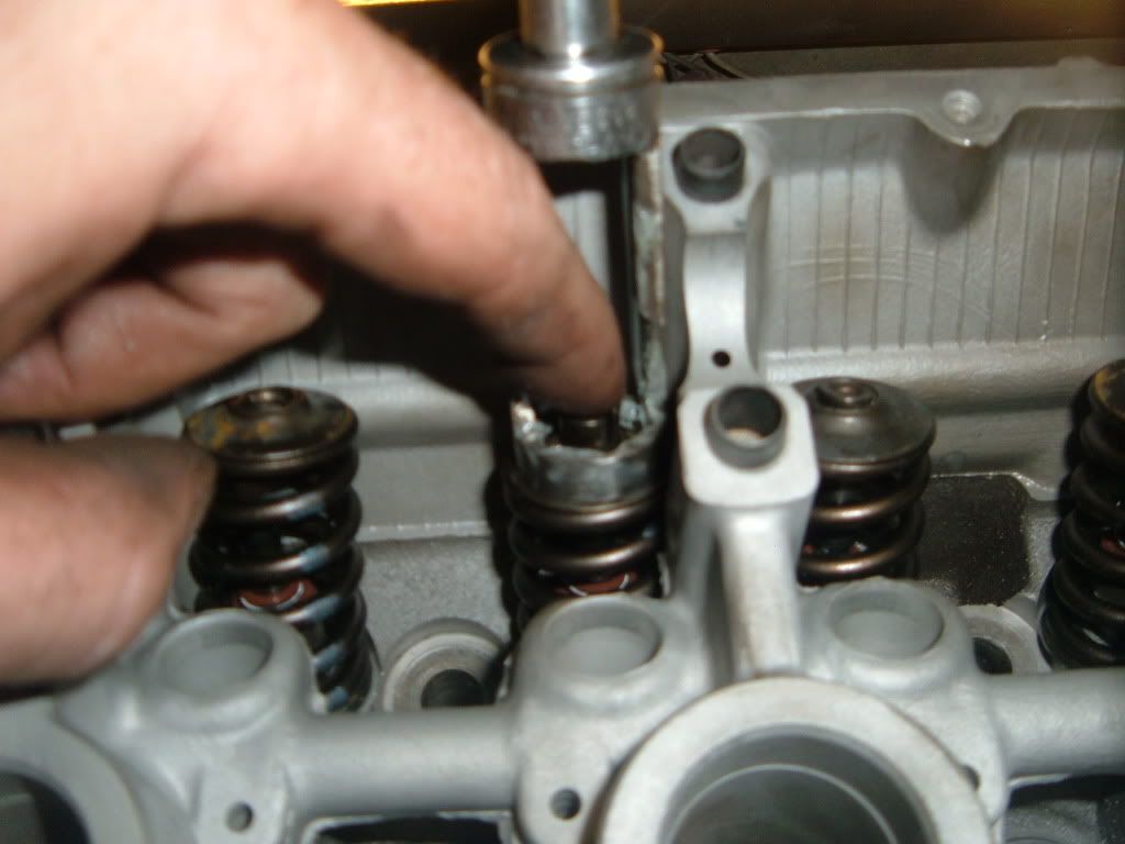
Fish the valve locks out of the head casting with the pocket magnet.
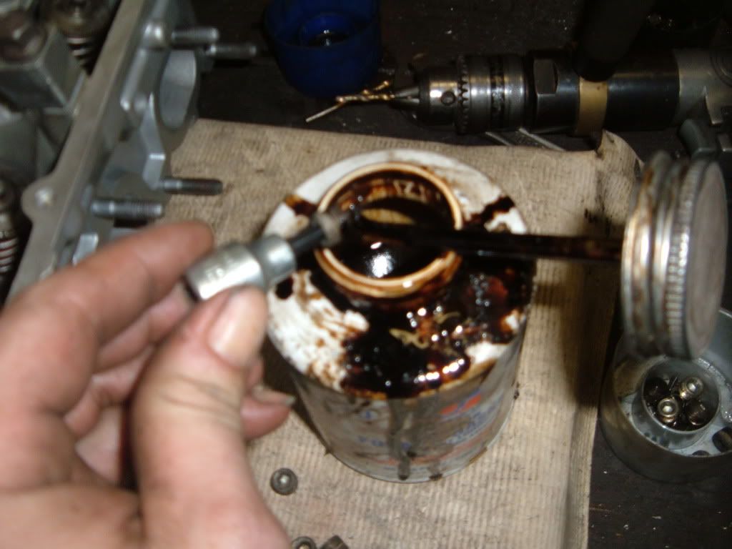
Place the valve locks in the paint can cap.
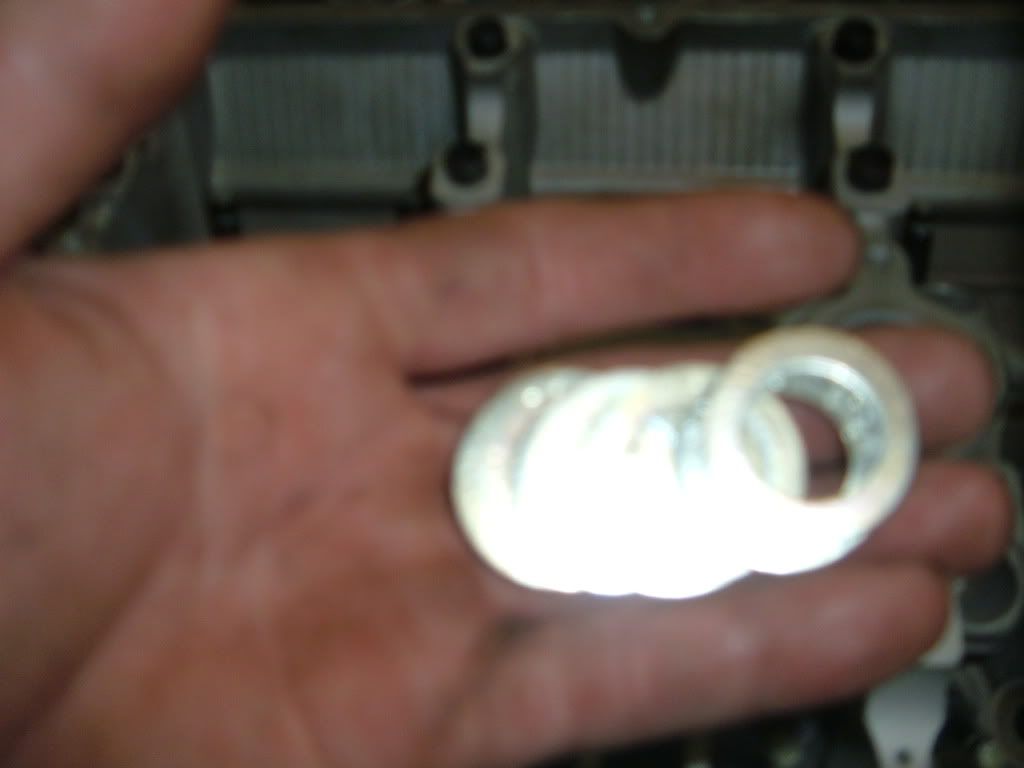
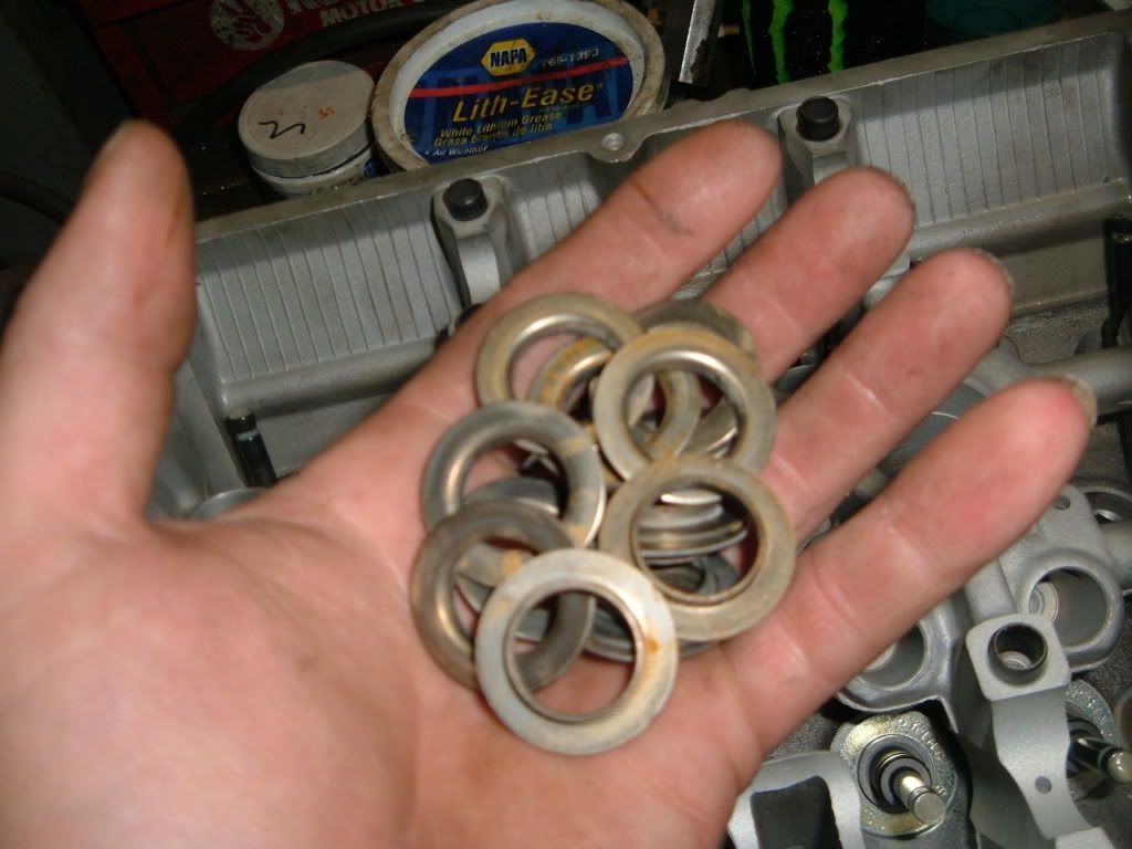
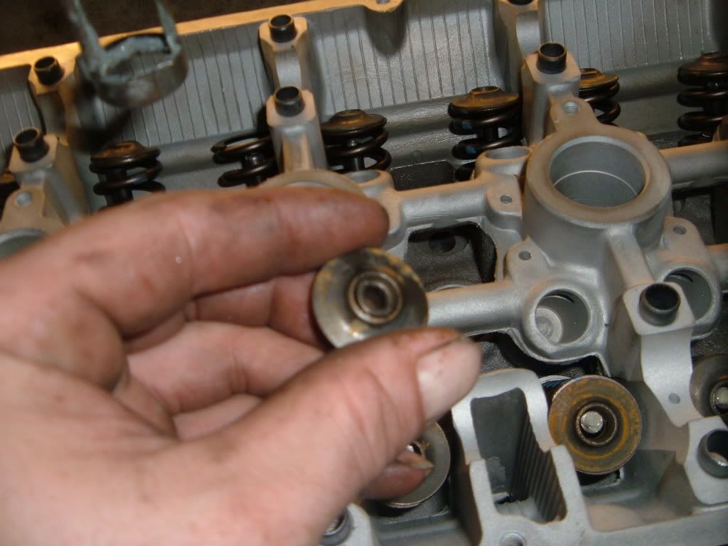
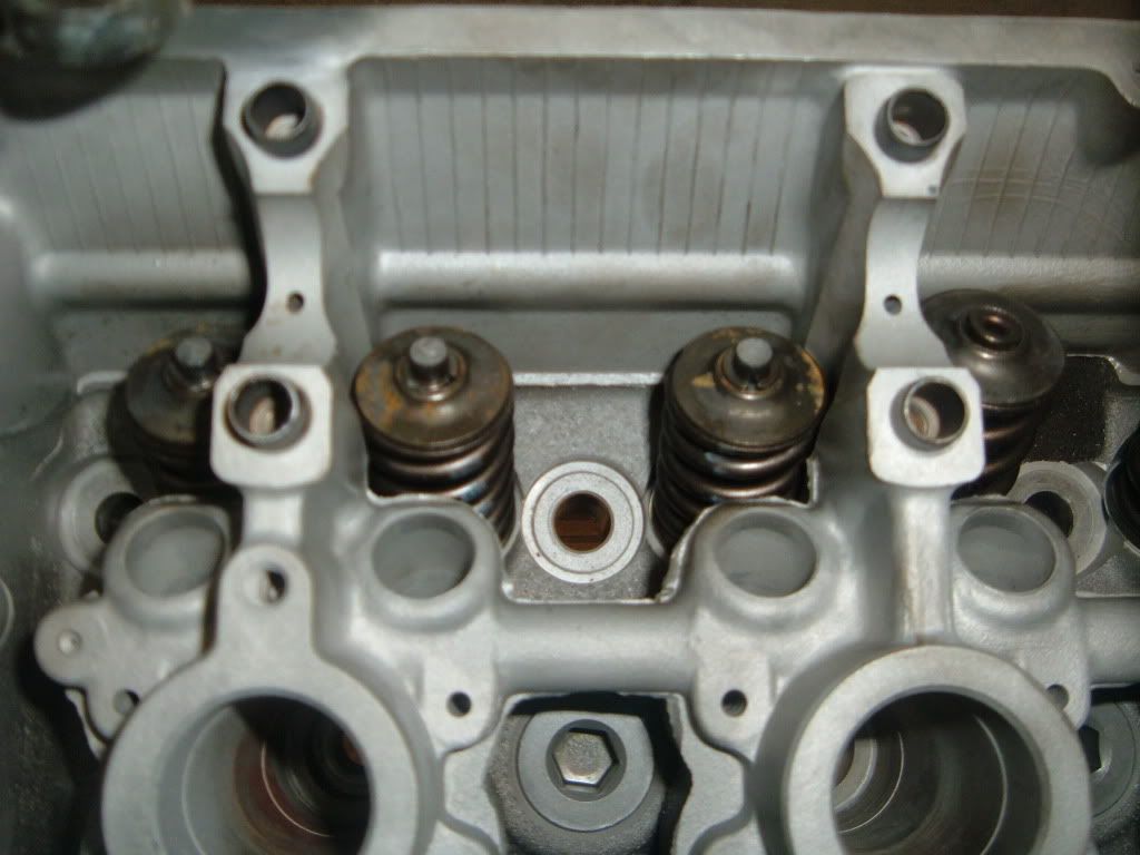
Now remove the spring seats with the pocket magnet and place in the spring basket to be cleaned.
Next roll the head over and remove the valves and place in the basket.
This head was rebuilt once before, it must have had bent valves.So I will change the valve guides.
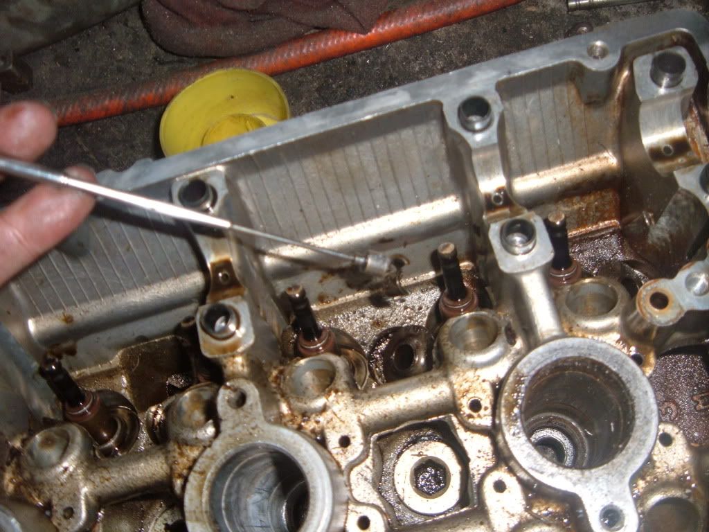
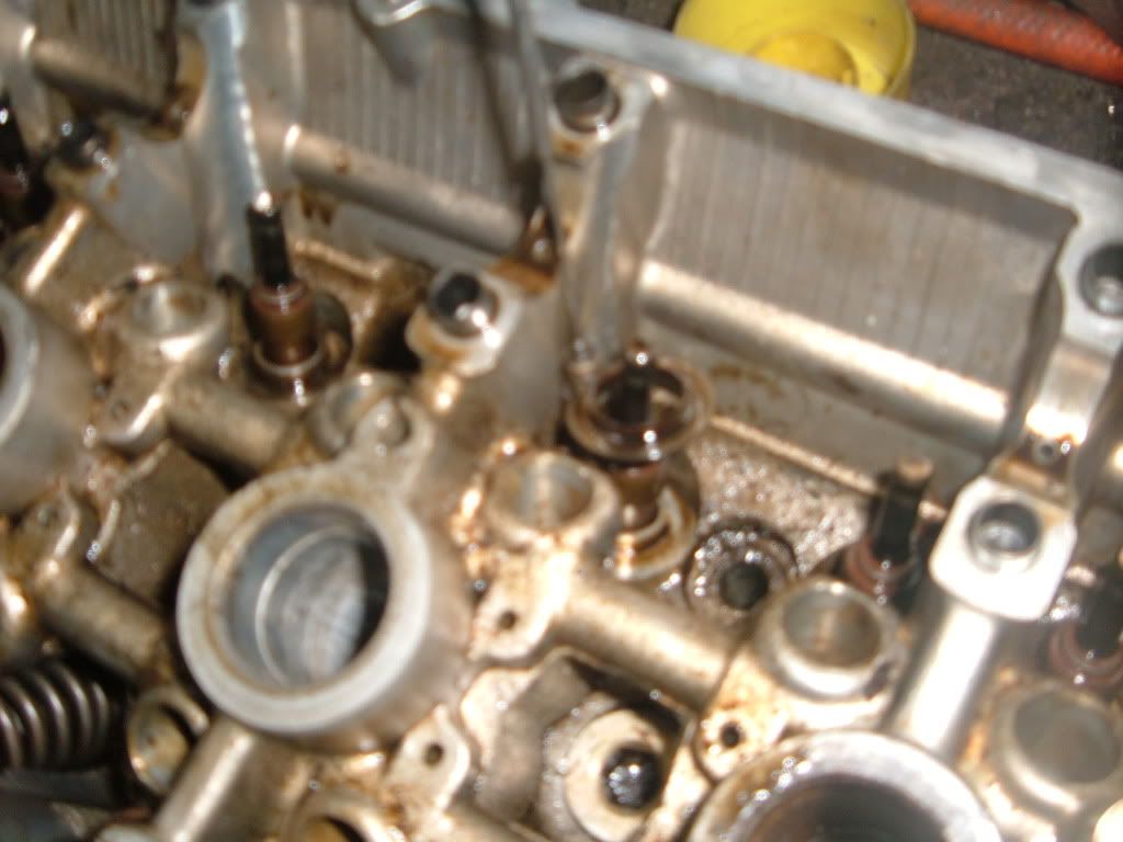
Now roll the head back over and remove the valve stem seals, throw these in the trash.
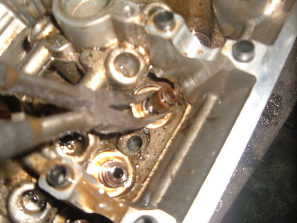
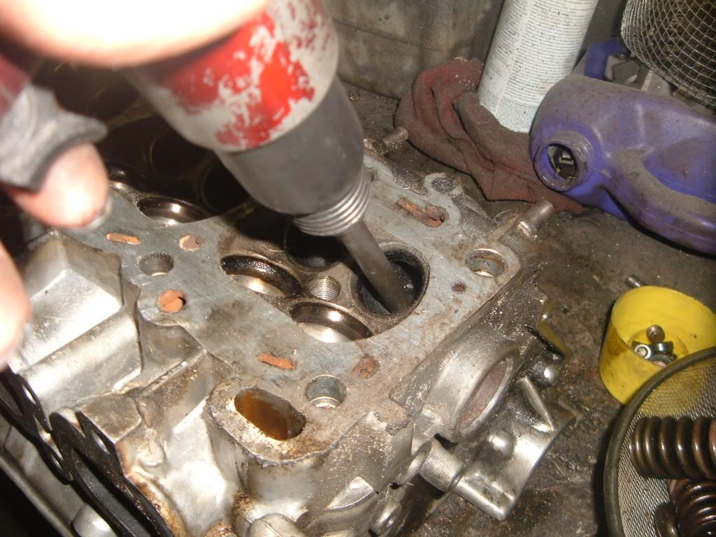
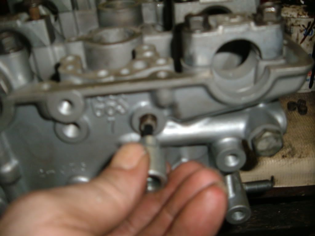
Next grab the 5mm allen bit and remove all the oil galley plugs. Keep these to be installed later, place in the paint cap with the valve locks.
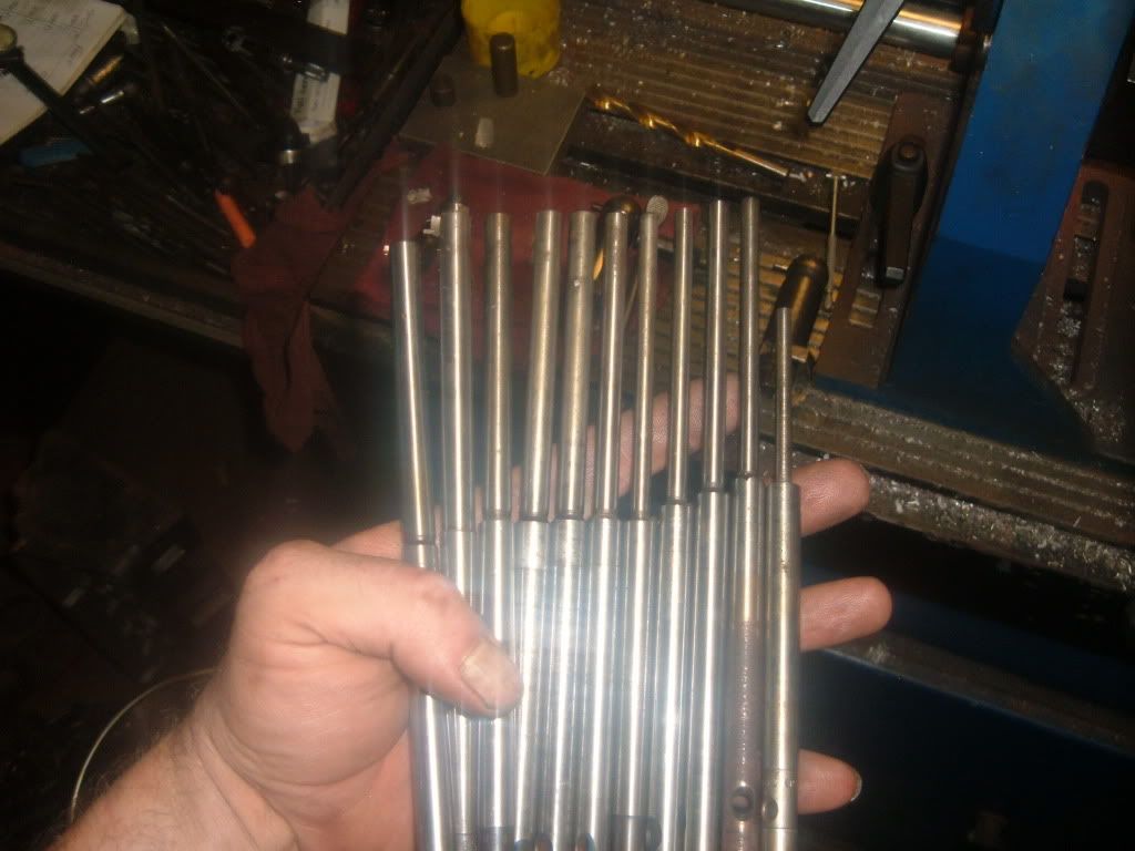
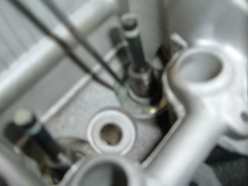
The last thing done is to remove the cracked valve guides.
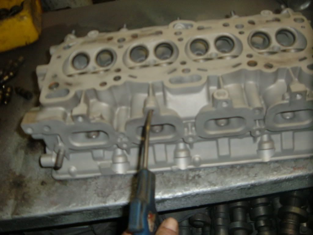
Now that the head is fully stripped, it can be tech�ed
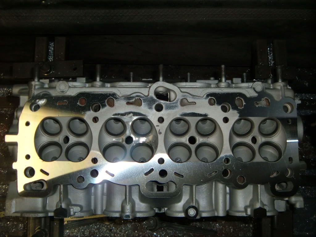
First thing is to do a quick clean on the head gasket surface.

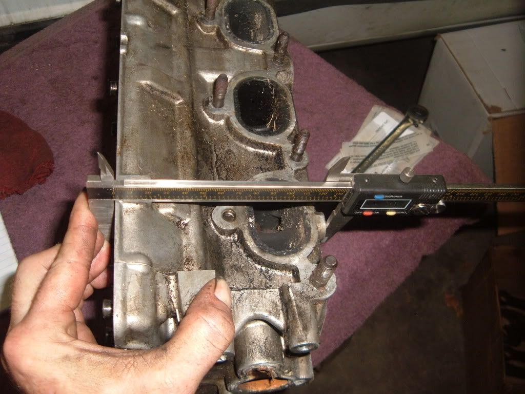
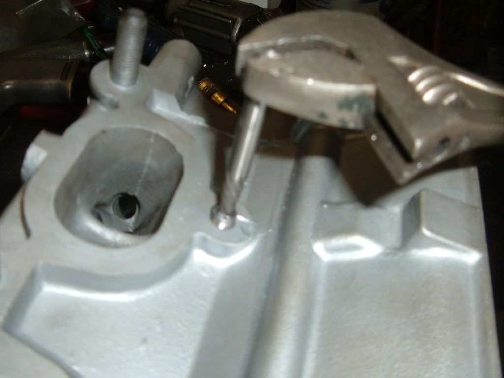
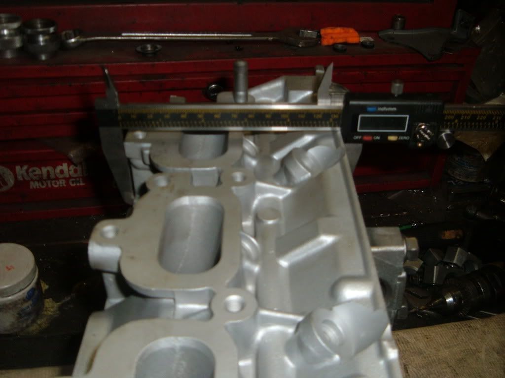
Next is to measure head thickness.
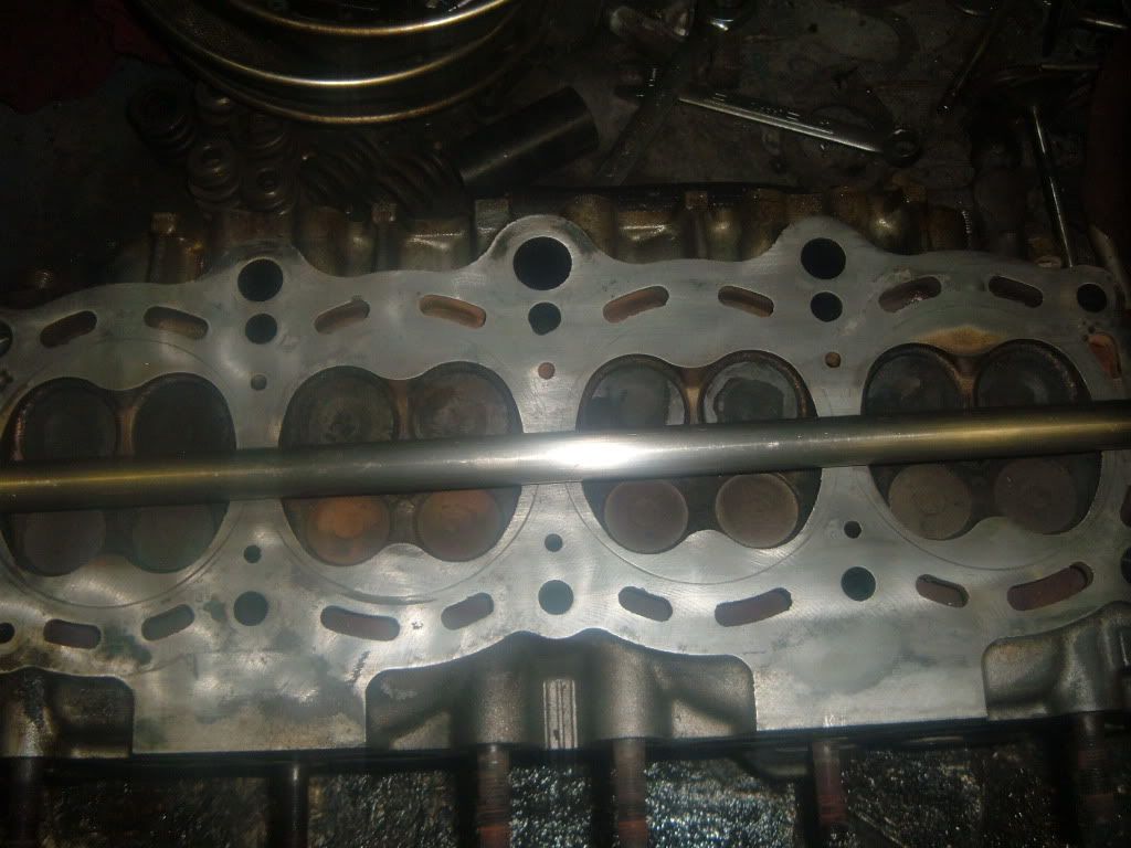
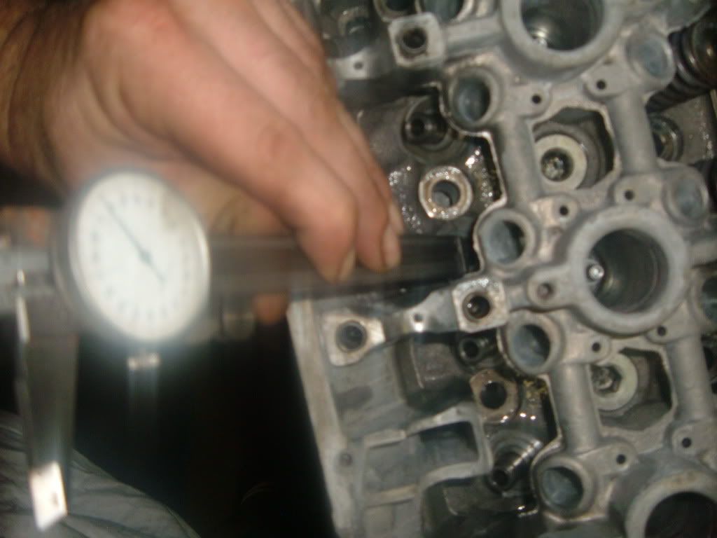
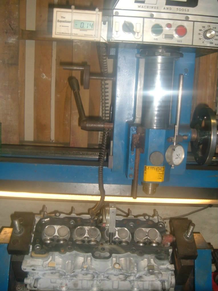
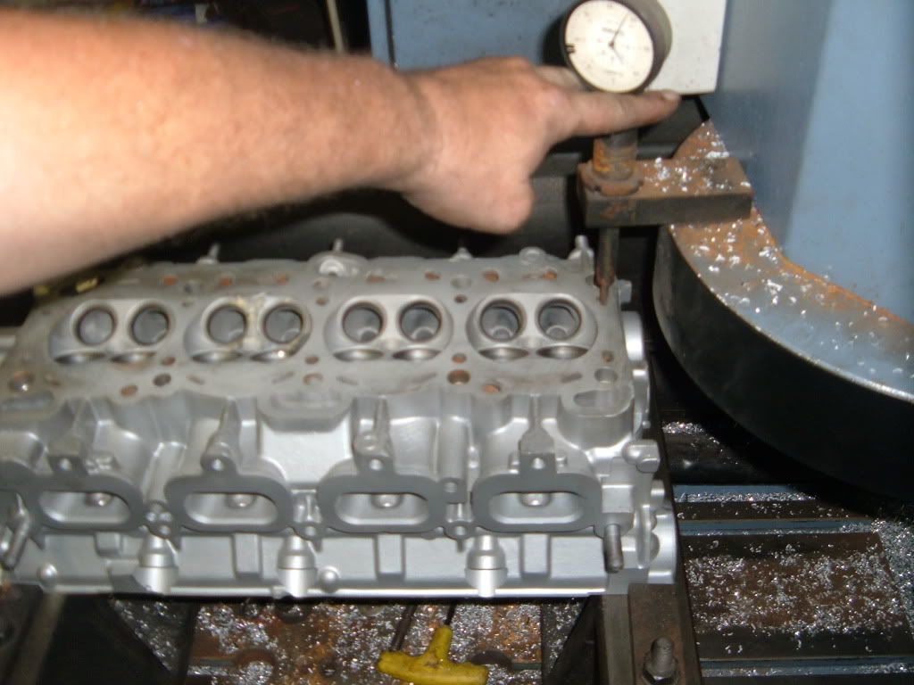
Now to check to see how bad the head is warped.
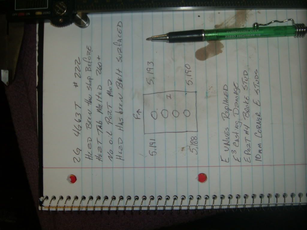
Notes are taken to reference back too.
If it all checks out, it goes to cleaning.
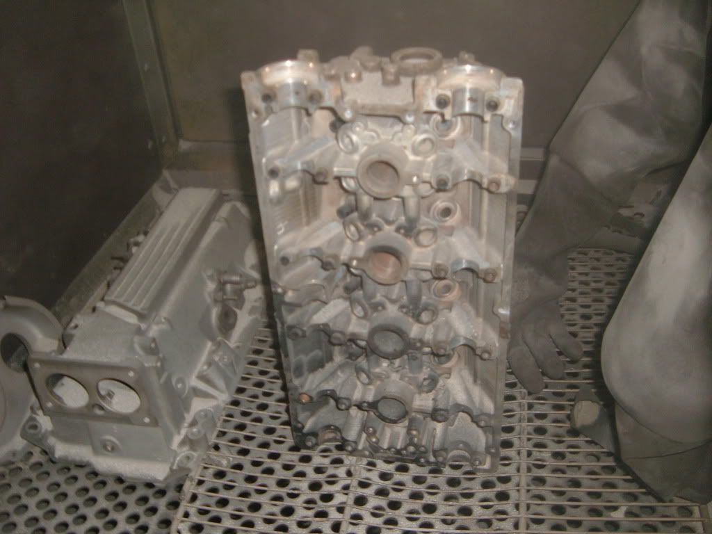
It gets thermal cleaning, then glass beaded.
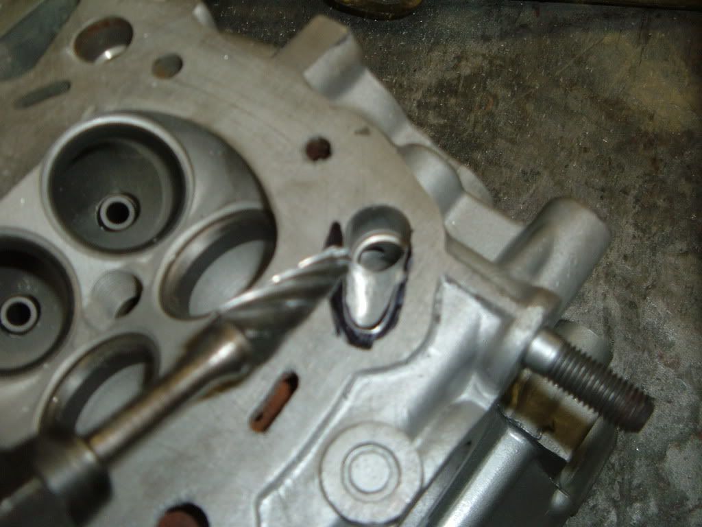
Next oil port mod #1 is done
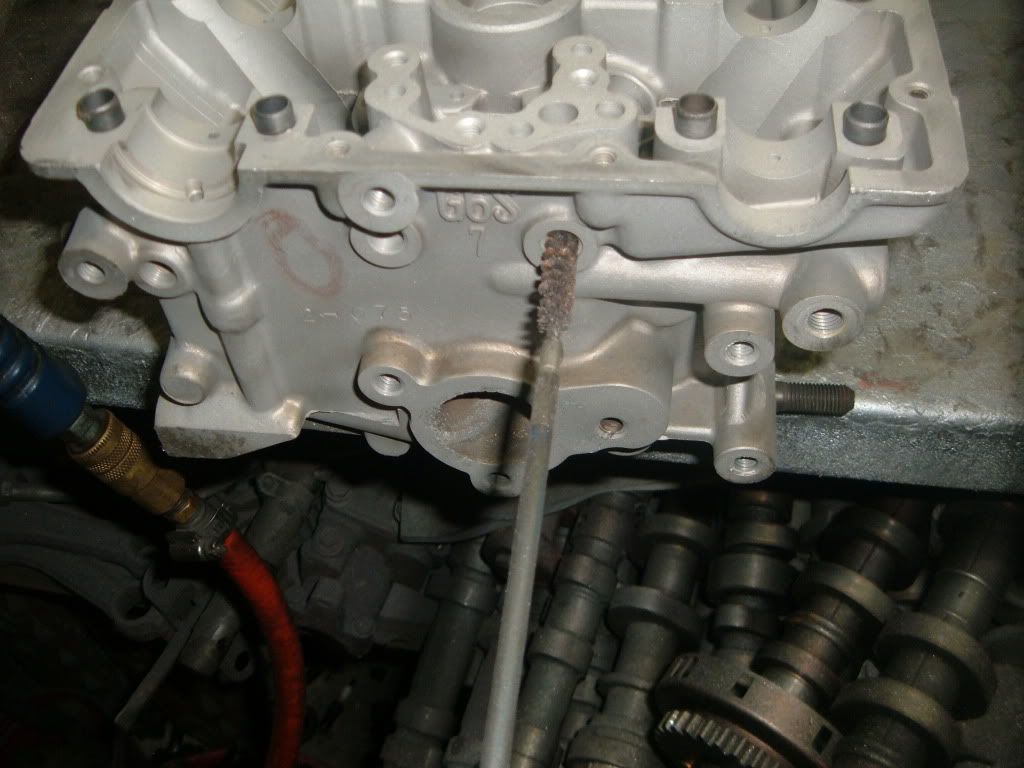
Next all the oil galleys get gun brushed
Now the entire head will be blown off with compressed air, including every bolt hole to make sure there is no glass bead media is left in or on the casting.
next is a coat of spray paint to seal the casting.
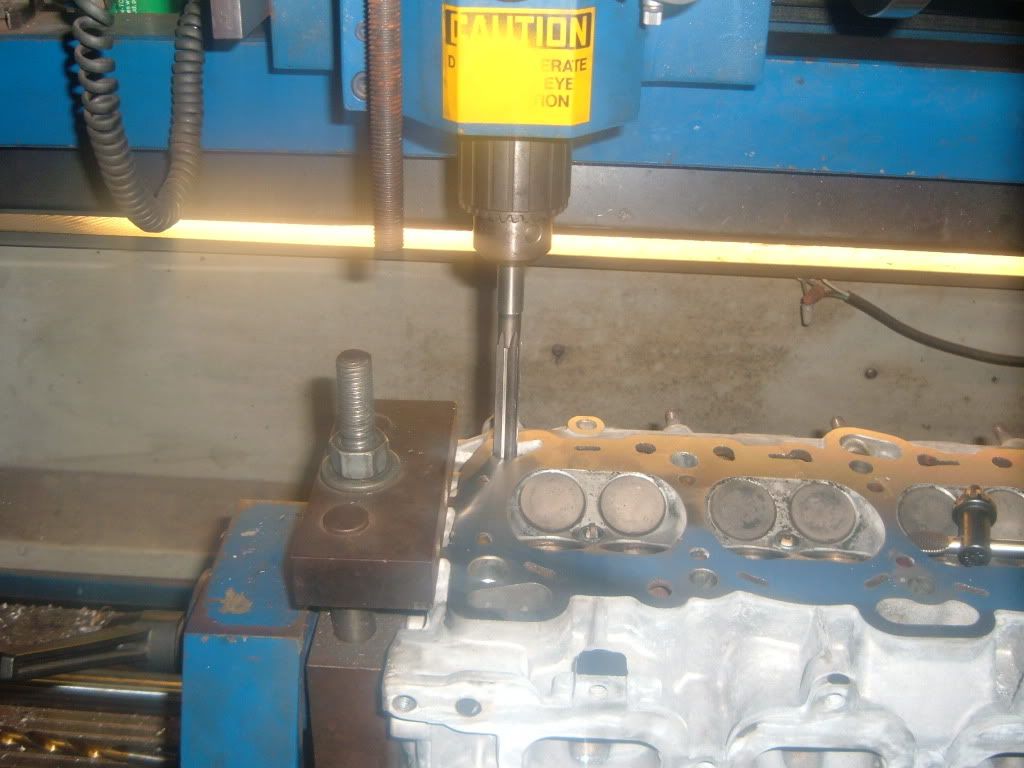
Now new guides can be installed.
They are set to height.
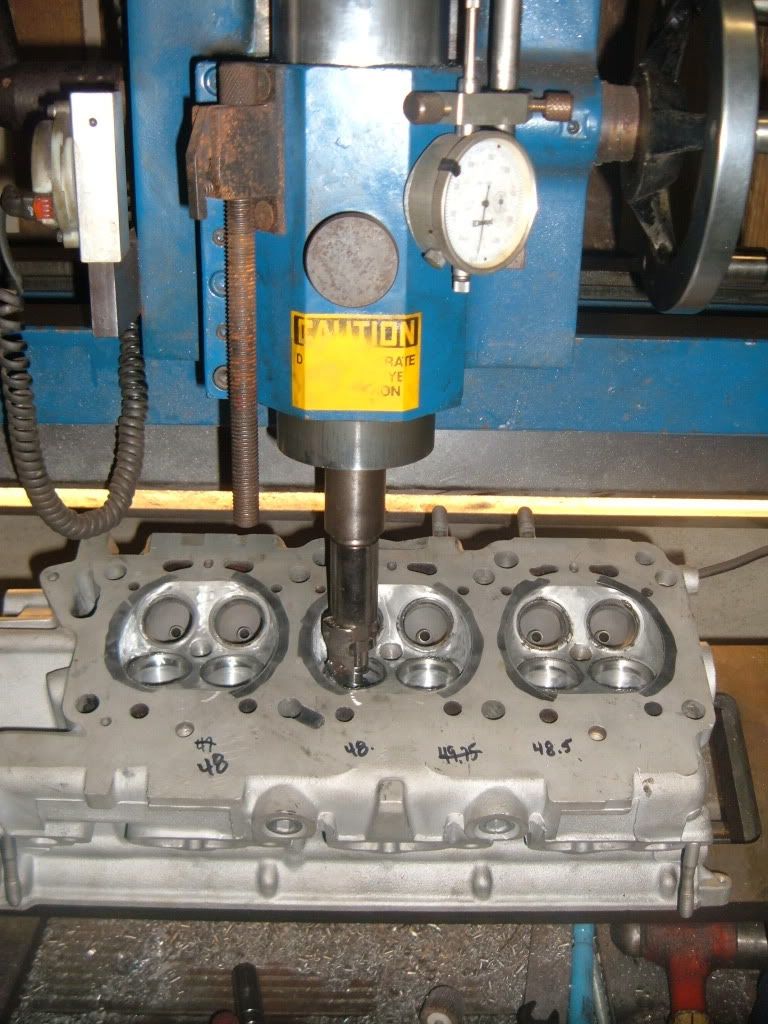
Now the valve seats can be cut.
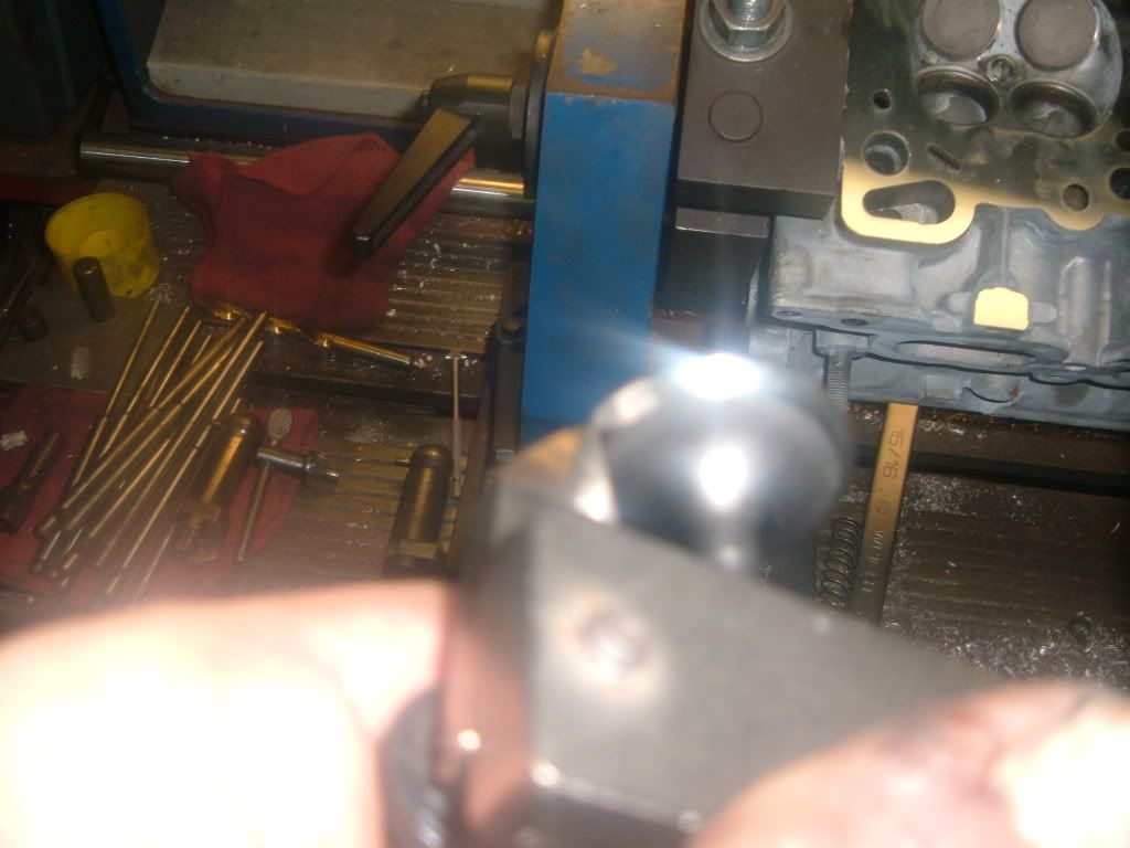
Fist is to set the head in the machine and secure it properly.
The proper sized pilot is selected.
The head is now leveled in the machine.
Now to set up the seat cutter.
First is to find where the seat is to make contact on the valve.
Now the cutter bit can be set.
The seats are cut.
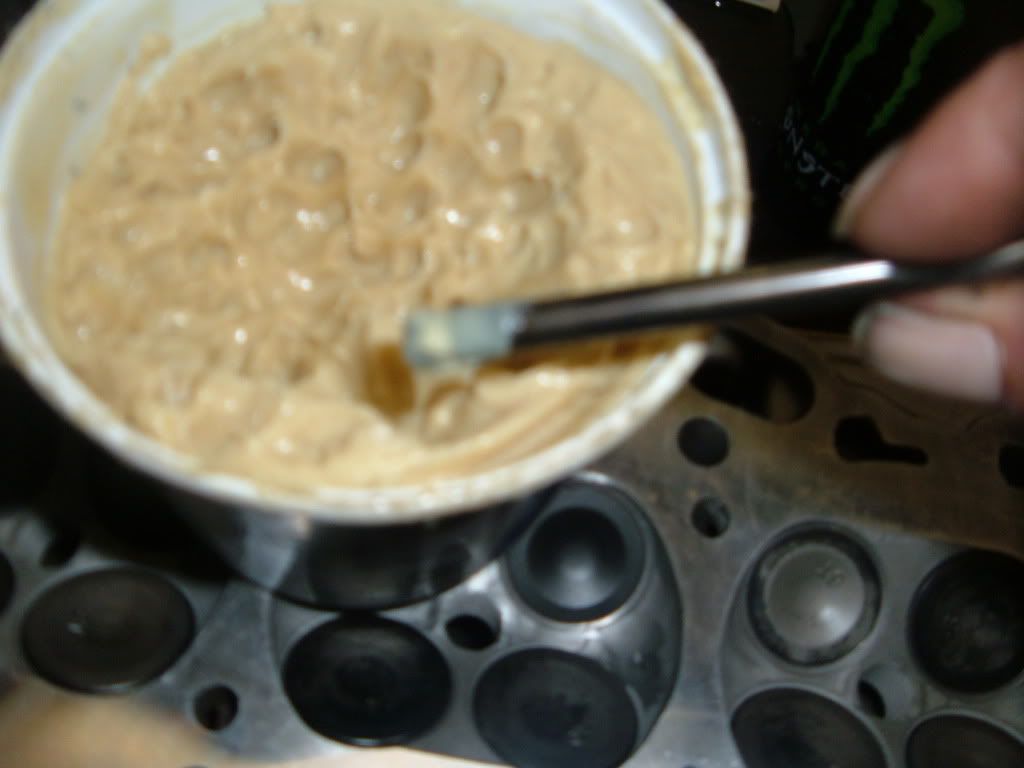
Now the valves are lapped.
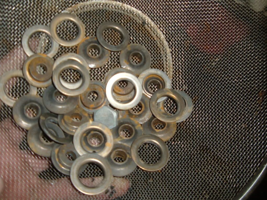
The small parts of he head have been cleaned, retainers, springs ect.
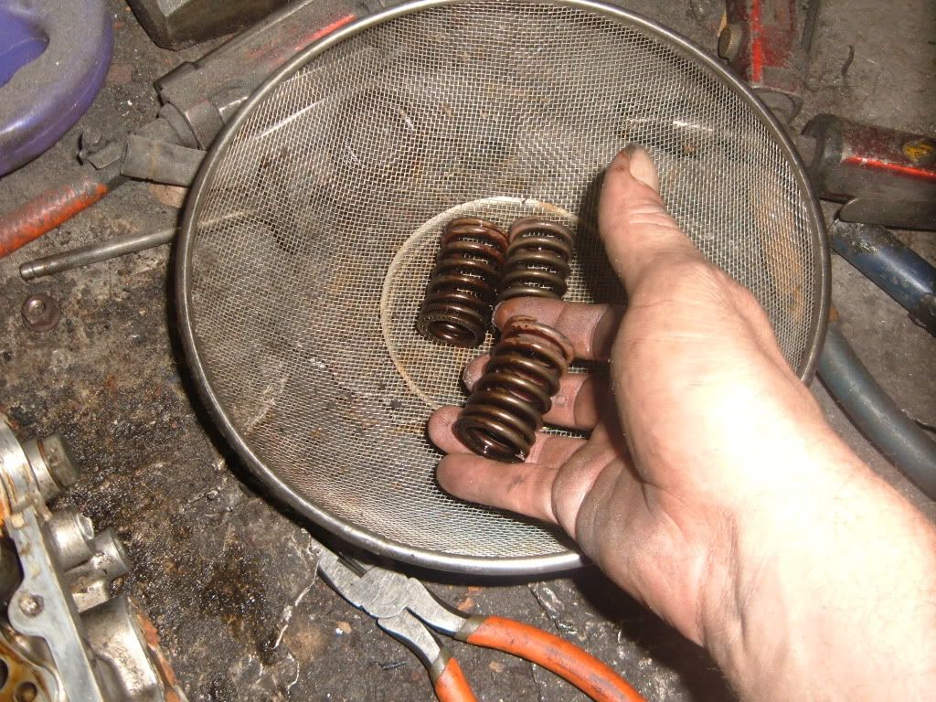
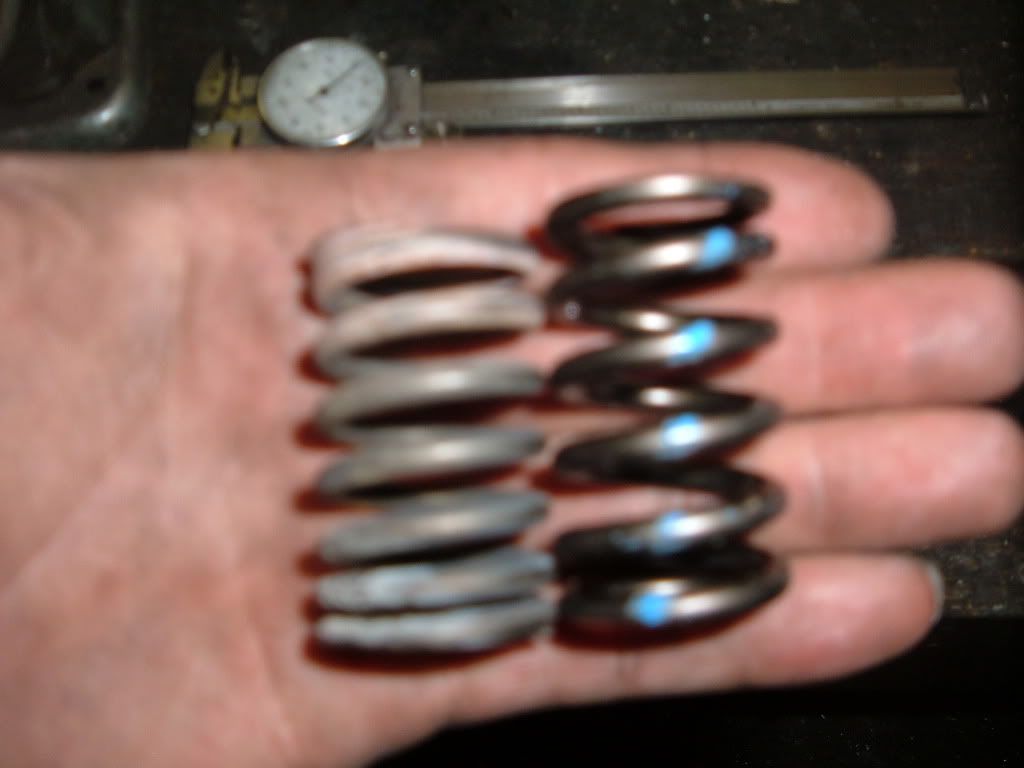
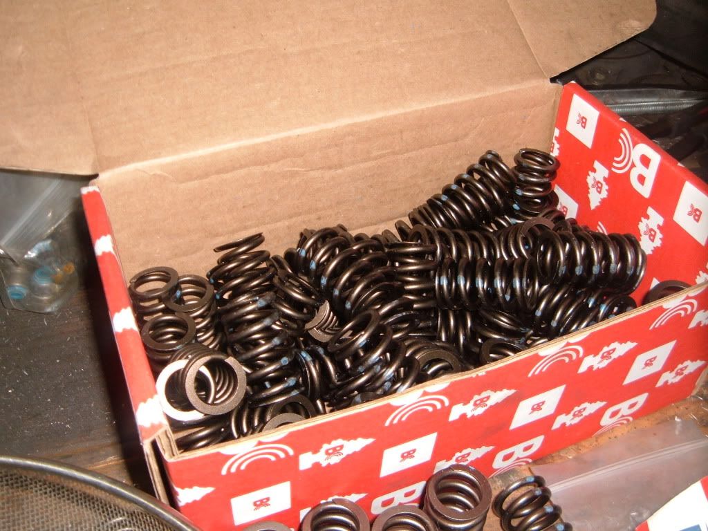
Valve springs are tested.
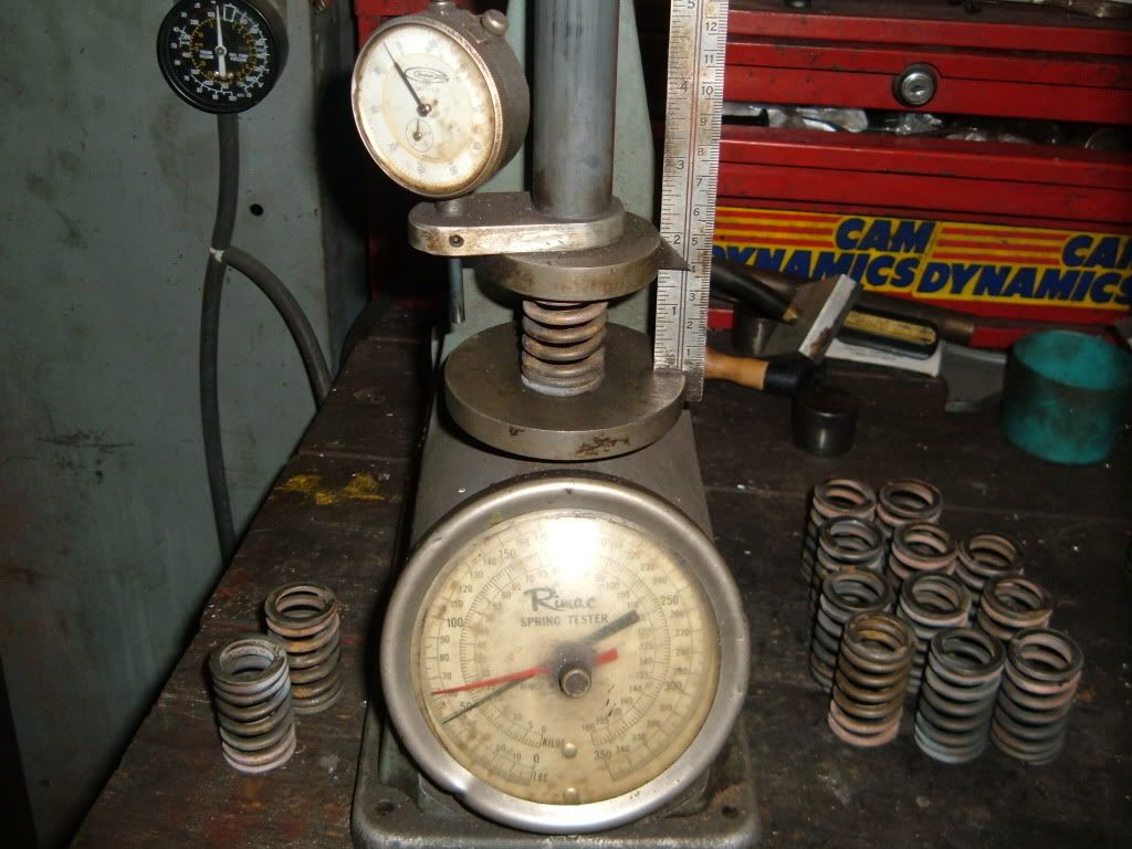
Most valve springs have been found weak, so New BC1100 springs will be installed
(stock spring on left, BC spring on right)
A broken exhaust stud was found and removed.
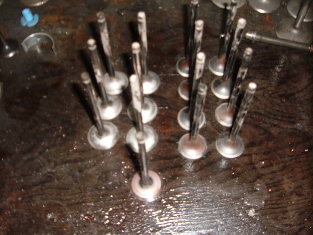
The valves are ground.
Ground and ready to be installed.
Now the head can be surfaced.
First Not all shops have the same equipment and the procedures from one shop to the next can and will differ.
Some shops cater to domestics and others imports or even diesels.
Some shops will view everything as a �stock� rebuilds.
So�.
The most important thing to know is the shop you use and the equipment they will use.
The subject head is a Mitsubishi 4G63 7 Bolt
The first thing that should happen is the machinist looks at the head. Checking for the obvious damage, broken bolts, stripped bolt holes, bent valves, ect.
At this point it is up to you as the customer, inform the shop what you want done, such as�
1) Pressure test for cracks
2) Valve job
3) Surface
4) Guide work
5) Any performance work wanted
Also now is the time to speak about who will provide what parts, valves, seals, guides, springs, ect.
Now the shop should be able to give you, the customer, an approximate estimate of what the parts and labor will cost.
You as the customer have the choice to agree, or go somewhere else.
Now that your head is at the machine shop, and you have agreed to have the work done.
The first thing to happen is the head will be disassembled.
The tools needed are
Wire basket for small parts springs, valves, ect
Small container for valve locks
Valve lock release tool (socket method)
Hammer
10mm socket
12mm socket
12mm socket
Ratchet
5.5mm allen bit socket or wrench
Pocket magnet
Long reach needle nose pliers w/45* bend
Impact gun (not pictured)
Cam gears come off first, use impact with the 17mm socket
Next remove the cam tower caps, use impact or ratchet w/12mm socket.
Start at the ends working towards the center
Once the cam caps are removed, lift the cams out.
Next lift the roller followers out
Now you can remove the HLA�s
Now remove the oil spliter
Now remove any other small bolts
This is a �heat tab� Most machine shops use them.
The center will slide down at 240-250* and totally dissolve at 260*
Next is to remove the valve train.
Yes the same method that a lot of DIY people use are used in a machine shop.
Use a basket and a paint cap, have a pocket magnet handy too.
Have your �tool� and hammer ready to go
Place the tool on the spring retainer and give it a firm whack.
The locks will stay in the tool and release the retainer and spring.
Place the retainers and spring in the basket
Fish the valve locks out of the head casting with the pocket magnet.
Place the valve locks in the paint can cap.
Now remove the spring seats with the pocket magnet and place in the spring basket to be cleaned.
Next roll the head over and remove the valves and place in the basket.
This head was rebuilt once before, it must have had bent valves.So I will change the valve guides.
Now roll the head back over and remove the valve stem seals, throw these in the trash.
Next grab the 5mm allen bit and remove all the oil galley plugs. Keep these to be installed later, place in the paint cap with the valve locks.
The last thing done is to remove the cracked valve guides.
Now that the head is fully stripped, it can be tech�ed
First thing is to do a quick clean on the head gasket surface.
Next is to measure head thickness.
Now to check to see how bad the head is warped.
Notes are taken to reference back too.
If it all checks out, it goes to cleaning.
It gets thermal cleaning, then glass beaded.
Next oil port mod #1 is done
Next all the oil galleys get gun brushed
Now the entire head will be blown off with compressed air, including every bolt hole to make sure there is no glass bead media is left in or on the casting.
next is a coat of spray paint to seal the casting.
Now new guides can be installed.
They are set to height.
Now the valve seats can be cut.
Fist is to set the head in the machine and secure it properly.
The proper sized pilot is selected.
The head is now leveled in the machine.
Now to set up the seat cutter.
First is to find where the seat is to make contact on the valve.
Now the cutter bit can be set.
The seats are cut.
Now the valves are lapped.
The small parts of he head have been cleaned, retainers, springs ect.
Valve springs are tested.
Most valve springs have been found weak, so New BC1100 springs will be installed
(stock spring on left, BC spring on right)
A broken exhaust stud was found and removed.
The valves are ground.
Ground and ready to be installed.
Now the head can be surfaced.


Comment