Announcement

Collapse
No announcement yet.

Fuel injected B3 wasted spark ignition project with schematics and lots of pictures.

Collapse
X
 
  • Filter
  • Time
  • Show
Clear All
new posts

  • Fuel injected B3 wasted spark ignition project with schematics and lots of pictures.

    I built this ignition system because the B3 distributor would not fit in my RWD application. So far it has been trouble free for the past 18,000 miles. I cannot make any claims of performance increases of better fuel economy because I have nothing to compare it to. The only benefit I can claim is the ignition system is more or less maintenance free. Figure this project will take a week or so to build.

    This system may fit other B engines and is not limited to the B3.

    Miata CAS (Crank Angle Sensor)
    Saturn S series coil pack
    Saturn S series coil pack wiring pigtail
    Saturn S-1 series ignition wires (single cam engine)
    Custom circuit board that you build
    New internal CAS rotor that you fabricate.
    * Miata CAS wiring pigtail or an extra fuel injected festiva distributor wiring pigtail.


    Tools:
    Hand tools.
    Cutting tools
    electrical tools
    Dremel with thin cutting wheels.
    Soldering iron
    files

    This system was originally built to work with the stock Festiva ECM and it will work with Megasquirt. Unfortunately I don't know the RPM limit (if any) but it worked well at WOT on the B3. If you have a factory tachometer in your Festiva I dont know if this will upset the tach or if the tach will continue to work.

    Before I get into the nuts and bolts of this project, let's talk about parts. Short cuts may be possible but in general you can expect trouble free operation if you use the parts I recommend.

    The coil pack should be off of a Saturn "S" series car built between 1996 and 2001. Others may work, but Saturn parts are dirt cheap at PnP. The coil pack that you want to use needs to be "dumb" and needs to have the amplifiers (ignitors) built in.

    My car uses 1994 miata coilpacks, but I don't recommend using them. They are expensive and rare. I wired my car to use both the saturn and miata coil packs. I ran the car with both types of coil packs and eventually chose the miata coilpacks because they will allow the Miata tachometer to work.

    The ignition wires are important, See if you can grab "stock" Saturn wires from the PnP. Stock wires have "Packard" written on them. Aftermarket wires will work for about a year and then start leaking. OEM wires work forever, or so it seems. My 96 Saturn has over 230K miles on the second set of wires and continue to work well. I'm also a member of a Saturn forum and nobody has ever had good results with "high performance wires" The only alternative is NAPPA wires. Everything else sucks, even Bosch.

    You want to grab wires from a S-1 single overhead cam engine. The wires from a twin cam engine S-2 will not work.

    For this build, the miata CAS needs to be from 1994-1997. The 1989-1993 CAS may work but the modifications are different. Educate yourself on the two different CAS systems and decide for yourself. It appears that the early CAS is easier to modify but I have not done it.

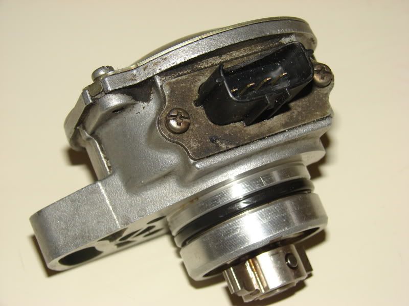
    The 1994-1997 miata CAS is more or less a fuel injected B3 distributor base without a distributor cap. If you look inside a fuel injected Festiva distributor you will see provisions for a second hall effect sensor. Unfortunately the second hall effect parts are not present.

    Finding a Miata CAS at a PnP is difficult, but some of you may have luck. Ebay is probably the best bet.

    Gather your parts, I'll wait...........

    Ok, times up.

    Let's build something!
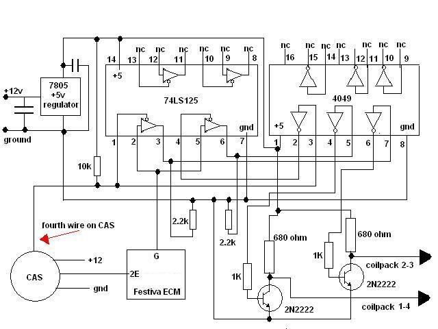


    This is the circuit that allows the CAS to work on a Festiva. This is a dumb circuit, meaning it has no intelligence and simply "gates" the signals. The CAS will plug into the Festiva harness without issues, however you will need to add the "fourth wire" The +12V , GND and 2E connections are made by the Festiva harness and are shown for clarity but are not action items.
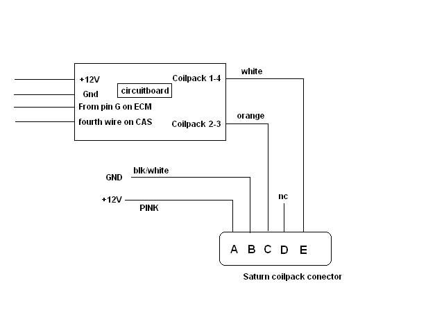


    This picture shows how the signals interface with the circuit board and the Saturn coil pack.
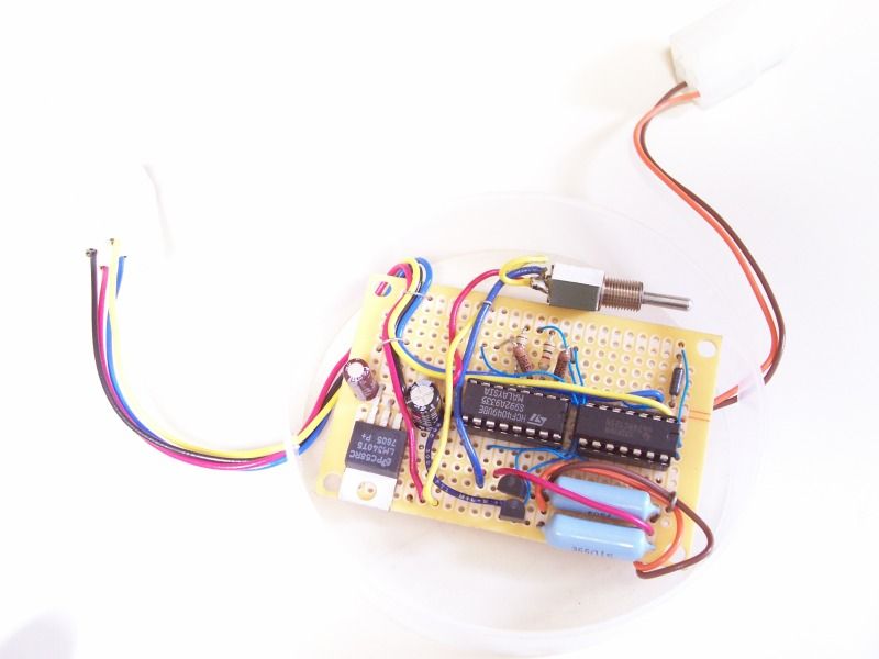


    This is the actual circuit board. Its built on a radio shack proto-board. The switch is not required and was used for development.


    Continued....
  • #2
    We will start with the easy stuff and progress to the difficult stuff.

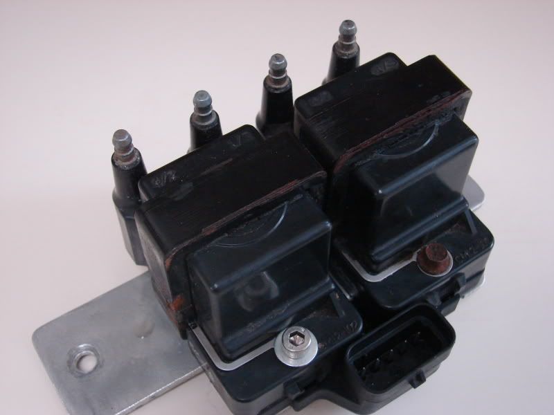
    The Saturn coilpack needs to be mounted on a aluminum plate to sink the heat away. If you went to the PnP to grab yours, you probably noticed the coil pack was mounted to the transmission. I actually have no idea where to mount the coil pack in a Festiva and someone should jump in and recommend a good location. Figure the location needs to be close enough for the Saturn spark plug wires to reach.


    Modifying the CAS,

    As previously indicated, the 94-97 Miata CAS is virtually identical to the fuel injected B3 distributor. The only real difference is the Festiva distributor lacks the second set of hall effect sensors. The Festiva harness will plug into a Miata CAS but the the Festiva harness lacks the fourth wire. The missing fourth wire is a unique issue I have not documented. For now, let's assume you dig out this missing wire from an extra Festiva distributor harness. Plug the missing fourth wire into the empty hole on your Festiva harness. I'll update this thread with more info on this if necessary.


    First of two internal CAS modifications.


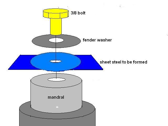
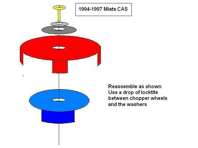
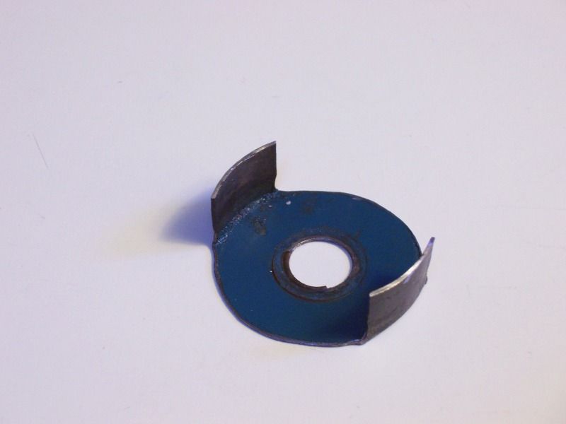
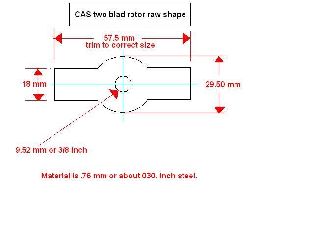
    The inner two bladed chopper wheel needs to be replaced with a custom one. This could be a deal breaker because it requires fabricating a mandrel to pound out a new steel chopper wheel. You cannot use the original chopper-wheel because the blades are of different sizes. The original chopperwheel would require a microprocessor to handle the signal.

    Take a look at the mandrel I have pictured. The diameter is 32.23 mm. The length of the shank is 30 mm and isn't critical. The overall length of the mandrel should be about 100 mm or 4 inches because you will need to mount this mandrel in a vice. The hole in the center of the mandrel is drilled and tapped 3/8 course thread bolt.

    I made my mandrel on a crappy lathe with a scrap piece of aluminum. A machine shop could make one fairly cheap.

    The raw material you will need for a new two bladed chopper wheel is .76 mm thick steel. You cannot use aluminum because the chopperwheel needs to interact with hall effect sensors and the material has to have magnetic properties.

    When I made my chopper wheel, it was on a Sunday afternoon and I was in a hurry. I looked around the garage for a suitable piece of steel and finally settled on a tool box lid form my makita drill. Galvanized sheet steel from Home Depot will also work.


    However you decide on fabricating this part, it is important that you maintain the center mark. I recommend starting with a punch and dimple the steel deep enough for a compass pointer. Scribe your lines and carefully. Once all the lines are scribed, it is recommended that the center be drilled to 9.52 mm or 3/8 inch. Drill a pilot hole and step up the holes with ever increasing drill bits until the desired size hole is reached. A step drill bit works great. Once the hole is drilled you can cut this part out with a demel with a cutting wheel attachment. Its hard to do, but it can be done. Figure on using at least four cutting wheels.

    Mount the steel to the mandrel using a large fenderwasher and a 3/8 bolt. Mount the mandrel in a vice. use a propane or MAP torch to heat up the metal and lightly tap the chopper wheel into shape. I recommend using a small ball peened hammer... extremely light weight. A carpenters hammer is too big but if you are careful you may be able to use one.

    Once you get the chopperwheel in the rough shape you will need to trim off the extra material. the blades need to drop about 10.5 mm or .400 inch. Mark both blades and cut them off with the dremel. Tip... I used a hose clamp tightened around the chopper wheel while it was still in the mandrel as a guide.

    The two bladed chopper wheel is ready to install.


    Comment


    • #3


      This is a 96-01 Saturn coil pack mounted to a heatsink. The heatsink I have pictured was fabricated from aluminum. The shape and size depends on the location you plan on mounting it to.


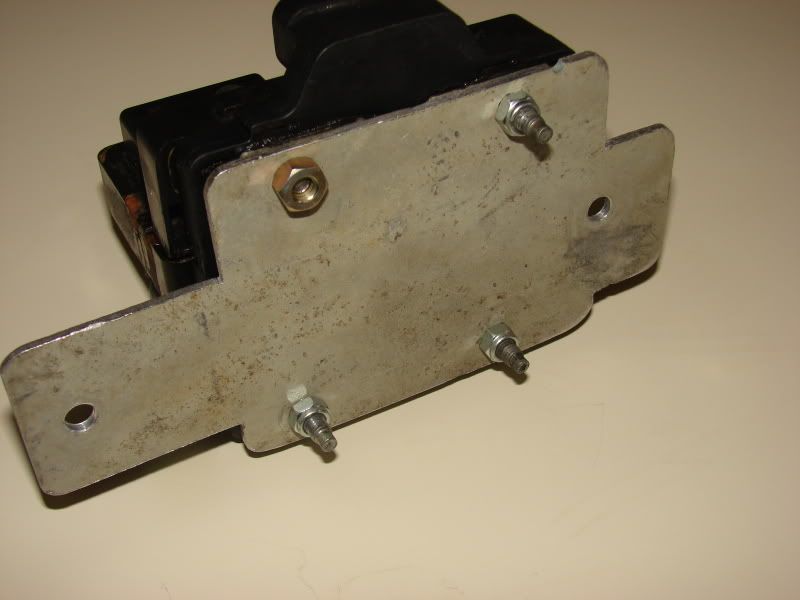
      Bottom of coilpack


      1994 Miata CAS "Crank Angle Sensor"

      The CAS will need additional modifications to get the base timing in approximately the right position.
      The modification requires that the four bladed chopper wheel be indexed slightly. I will upload the latest photo of this mod soon.

      Jim

      Comment


      • #4
        I love to read and hear about this amazingly inventive stuff and you are detailed to the extreme! But me, as a mere Luddite trying to escape from 20 year old, and increasingly unreliable electronics, how much real difference is there between gas mileage between an entirely mechanical-carbed B3 and a sophisticated/electronically-governed B3?

        Comment


        • #5
          To fujioko:

          HOLY CRAP!, there's a lot of smart people on this board! :salute:
          88L - 'Twistiva' - 'The Fusion of Man and Machine'
          88LX - 'Laztiza' - Future Resurrection Project
          91L - 'Mistiva' - My Daughter's DD
          93L - 'Vextiva' - Airport Car

          Comment


          • #6
            Good question Bert,

            I'm not a Festiva expert but decided to use the fuel injected B3 in my ultimate gas mileage Miata project. Some folks like to keep it simple and others need to explore the boundaries. Overall its probably cheaper to do nothing and keep the Festiva in proper tune.

            Since my project is based on a different car, I cannot make any claims to improvements to an actual Festiva. I personally would like to know if anything I have done is an improvement to a Festiva and perhaps someone will try and find out.

            Jim

            Comment


            • #7
              Epic! I can't wait to try this!
              Going old school...

              89L Carby FIDO, previously owned by FestivaFred

              Comment


              • #8
                Originally posted by fujioko View Post
                I'm not a Festiva expert but decided to use the fuel injected B3 in my ultimate gas mileage Miata project.
                I was looking at this thread thinking "I'm pretty sure I saw something like this on Miata.net". Awesome info, didn't realize that you were a member here too, I was following your MPG Miata build over there. Used to have a '92 SBY but ended up selling when I bought my Camry wagon. Great project, I may do this if I ever get the ball rolling on my RWD festiva project.
                No festiva for me ATM...

                Comment


                • #9
                  Fuel injected B3 wasted spark ignition project with schematics and lots of pictures.

                  Very cool! Would coil on plug be possible? I just found Toyota echo/yaris cops have igniters built in. Issues with mounting them to the head and the heat from the exhaust manifold popped in my head though. Cops would eliminate spark leak from the wires though.
                  -Zack
                  Blue '93 GL Auto: White 13" 5 Point Wheels, Full LED Conversion, and an 8" Sub

                  Comment


                  • #10
                    Originally posted by crazyrog17 View Post
                    Very cool! Would coil on plug be possible? I just found Toyota echo/yaris cops have igniters built in. Issues with mounting them to the head and the heat from the exhaust manifold popped in my head though. Cops would eliminate spark leak from the wires though.
                    Good question!,

                    The major issue is COPs use a shorter dwell time and would burn out within a half hour or less.

                    The Festiva ECU generates a signal with a dwell time of approximately 5ms and COPs only need about 2ms. Most wasted spark coil packs are happy with a 5 ms dwell.

                    Megasquirt has adjustable dwell time so it can be programed to send the correct signal.

                    It is possible to slam the COP with a 5 ms signal but you need to do some math and add some high wattage resistors. The circuit has to be analyzed with AC rules. I don't know the resistors values off the top of my head but it is possible.... I think.

                    Everybody, Thanks for the comments and interest! I should have the remaining photos uploaded today or tomorrow. I wish everyone a safe and happy New Year.

                    Jim

                    Comment


                    • #11
                      Here are some more photos of the CAS project.


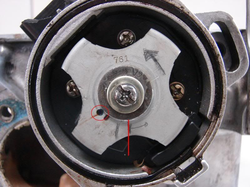
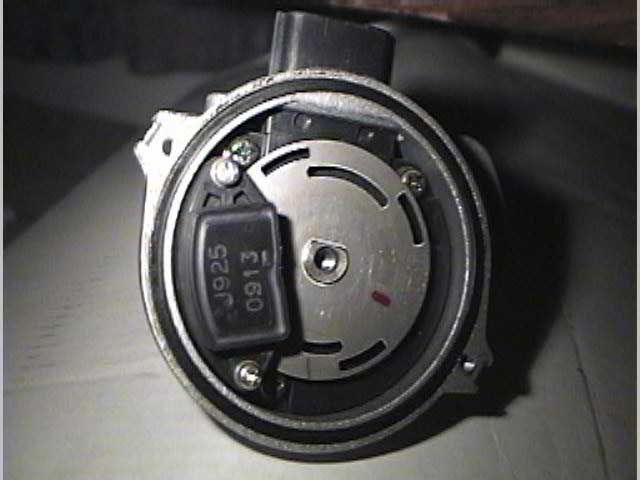
                      This is the 94 Miata CAS installed in the Festiva head. The camshaft is set to the TDC mark on the pulley.
                      This is exactly how my ignition was configured for timing. The four blade chopper wheel was slightly modified by filing the flat spot in the center to index it to this position. You want to get it as close to this as possible. The finial position will be adjusted by using a timing light and rotating the CAS like you would do with a distributor.

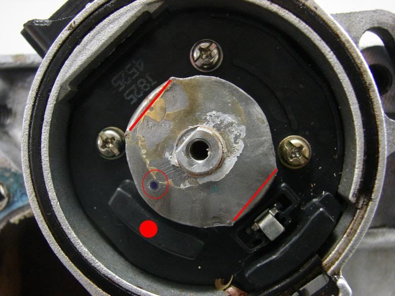
                      Notice the red circle on the left. The circle highlights the position of the two blade chopper wheel in the next photo.


                      This photo is different that the one I published last year on a different forum. I'm not sure why the position changed between photos but this is exactly how the car was configured and ran. Its possible that the last time I had the CAS apart I moved the rotor position for more timing options with the megasquirt.


                      This picture is of the CAS with the four blade chopper wheel removed. The red lines show the position of the two blades. The red dot shows the hall effect sensor that the two blade chopper wheel interacts with.


                      Here is the hand made two blade chopper wheel. you can still see the blue paint from the Mikita box this was made from.


                      This is an early Miata CAS,(90-93). As you can see it is totally different, however it appears that you may only need to do some minor modifications to make it work. I'm just providing an additional option and I have not tried to do this. The good news is it appears as though you would only need to enlarge one of the two slots to make it symmetrical. The slot in question is obscured by the sensor and I'm not really sure what it looks like.


                      Ok, one last minor issue.... It has been a while and I have done a lot of undocumented work on this project. I'm pretty sure The ignition phase was kept intact but its possible I swapped something along the way. Your car should start right up, but its possible you may have to swap 1-4 and 2-3 wires on the coil pack. The worst that will happen is the car wont start, or possibly a backfire.


                      Jim

                      Comment


                      • #12
                        How did you get so smart!!!!!!

                        sheesh i feel dumb, i don't think i have the intelligence to pull this off.

                        Comment


                        • #13
                          Why couldn't you have just chopped off two blades of the original chopper wheel? Is the sensor on the outside still doing its job since the blades don't spin as close to it?
                          2008 Kia Rio- new beater
                          1987 F-150- revived and CLEAN!!!
                          1987 Suzuki Dual Sport- fun beater bike
                          1993 Festiva- Fiona, DD
                          1997 Aspire- Peaspire, Refurb'd, sold
                          1997 Aspire- Babyspire, DD
                          1994 Aspire - Project Kiazord
                          1994 Aspire- Crustyspire, RIP


                          "If it moves, grease it, if it don't, paint it, and if it ain't broke don't fix it!"

                          Comment


                          • #14
                            Originally posted by zoom zoom View Post
                            Why couldn't you have just chopped off two blades of the original chopper wheel? Is the sensor on the outside still doing its job since the blades don't spin as close to it?
                            Hi 'ya,

                            The four blade chopper wheel generates the "fire" command. The smaller two blade chopper wheel is used to select which coil pack will fire.

                            Jim

                            Comment


                            • #15
                              Hi 'ya folks,

                              I'm going to be updating this thread with a simple solution to all the fabrication. This new system should be pretty easy to build.

                              I'll also post the dimension of all the brackets that are specific to Aspire/Festiva.

                              Stay tuned!

                              Comment

                              Working...
                              X