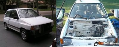
well for the last week i have been trying to wire up my gauges but last night i spent a solid 12 hours and am baffaled at the wirring. what im trying to do is hook up my electric fuel pressure gauge and boost gauge and also have the ability to expand once i get more gauges here is what i did. first off i pulled my dimmer switch i grabbed my test light and grounded it then i probed to find the hot dim wire so when i turned the dimmer the test probe light dimmed, so i took my dim wire and routed it to the center console. next i used a relay and fuse set up for my key on power, i chose to run a relay so that way i could run more gauges and they will be on there own seperate fusible circuit. for the relay i ran constant power to battery cable, i grounded the relay under the hood, i used a key on trigger wire that i found in the cluster (i used the test probe til one lit up with key on) ok so now i have a ground, key on power, and dim power. well i took my dim wire from the dimmer switch to the light bulbs and then put my ground on. now heres what happends with the dimmer switch off there is power to the gauge lights and with dimmer on there is no power. so then we where thinking of just stealing the signal off the heater control dash lights so i take my trusty probe and ground it. there are 2 wires on the bulbs in the heater controls i grounded my test probe and it seems as the polarity (positive and negative) switches when you turn the dimmer switch when its on ill have my probe on the positive i turn the dimmer switch and the other wire then becomes positive. so the only thing i can think is the polaritys are changeing. how does the dimmer switch work? what can i grab a wire to use for my dim??? i hooked a buddies tach up on his festiva and i tapped into his dimmer switch to, and it seems like the same problem with no head lights on the tach is lit and with head lights on it turns off. i will try to get some pictures and maybe a video. i hate wirring!!
Announcement
Collapse
No announcement yet.
wirring mess help!!
Collapse
X
-
You're making my head hurt. When you say "i chose to run a relay so that way i could run more gauges and they will be on their own separate fusible circuit", are you talking about power for the gauge or power for the light for the gauge? A lot of relays have both normally open and normally closed contacts. It sounds like you have the wires hooked to a normally closed set of contacts and when you apply power to the relay that set of contacts open and turn off your lights.You gonna race that thing?
http://www.sdfcomputers.com/Festivaracing.htm
Comment
-
You must remeber in some automotive interior lighting circuts they ( the switches) are controling the GROUND and not the hot, something to look into as I dont have the prints in front of me.money pit
No spitters were I work, you swallow it all. The Company feels if you already have it in your mouth why waste it.
Comment
-
ok that makes sense about the ground so i should hook the lights to a head light power source and then hook test probe to positive and probe the switch til i find the wire that dims? about the relay i was just using it to power the gauges them self there electric gauges but the light will be tied into the stock dimmer. i appreciate the help and ill let you know what happends. if someone knows off hand where to find a head light wire and what color to look for please let me know same with the dimmer wire my car is a 88 lx if it matters thanks all!!
Comment
-
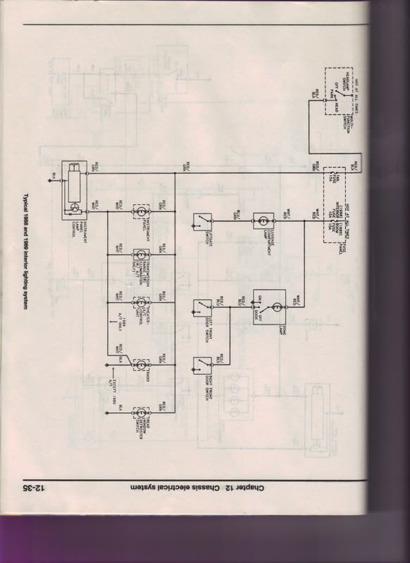
Your gauge illumination lamps CANNOT be grounded at the gauge. A separate wire for both the positive and negative (ground) must be installed. It's likely the gauge bulb gets it return path (ground) thru the gauge case and mounting bracket. The connector at the dimmer control has (should have) three contacts/three wires. Red/White, Red/GReen, and BlacK The dimming resistor is in the R/GR & BK circuit. Your GROUND ISOLATED accessory gauge lamps should be tapped into the R/W and R/GR. The number of lamps added to the dimmer circuit will cause additional current to flow thru the resistor thereby warming it up a bit more. Too many lamps might cause smoke to be released from the resistor. We all know when you let the smoke out of an electronic or electrical component it is a good indication of failure. BTW, I'm getting the wire colors from 1991 info. Let us know how you finally work it out.
Comment
-
Originally posted by Hot_Wheels View Postok so your saying grab my positive off the dimmer and my ground off the dimmer right?
Yes. Regardless of the colors. Can't imagine why the colors would change but I'm looking at my 91. Just be sure the lamps in your gauges are isolated from ground.
I never had the dimmer in my hands so don't know how it is built. Upgrading to one that can handle a lot more lamps might take some good old down home engineering. Units from other cars that had more dimable illumination might be a possibility.
Comment
-
ok heres what i did i took 3 jumper wires there are 2 hot wires when the lights are on red/green and red/white and there is a solid black going to stock harness and solid yellow to the swithc for what ever reason they changed the colors going to the switch so i know ground is black so one jump wire went there and then i used the red/green and red/white to power the light well when i used them the light stayed constant and didnt dim so then i switched the 2 positives around then the dash lights became real dim the switch got hot and my test light just stayed on constant and wouldnt dim what am i doing wrong? charlie if you gte any ideas call me 331 645 4730 im going to go back in the 100 degree garage in a second
Comment
-
LOOK TAKE ONE OF THE LIGHT's WIRE's HOOK IT TO CONSTANT OR SWITCHED +POS(depends if you want the lights to work when the key is off or on) TAKE THE OTHER WIRE AND HOOK IT TO THE WIRE THAT WHEN YOU DIMM THE LIGHT IT GOES FROM + to -! You can use the gauge bulbs like a test light in fact it's the same thing.
Or you could just connect one wire to the red/white and the other to 12V+!
Thanks
Comment
-
Hey Hot Wheels, looking at the diagram all you need to do is hook 1 wire from your gauge globes to the red/green and the other to the red/white. It doesn't matter which way around they go if they are incandescent (normal) globes as they are just a filament of wire and only need current passing through them, they don't care which way it goes. If they are LED's you cannot dim them so give up now.
Looking at the diagram the red/green is 12v from the headlight switch, the red/white is the ground through a variable resistor. Do not connect one side to power and the other to ground, it will just be full brightness.
The other thing you mentioned is that one globe goes straight to ground. I can not make out what the globe is for (need my eyes tested) but it would stay full brightness all the time and does not get dimmed.
If you wanted to have your gauges lit all the time you could get any ignition on power source you liked as long as you put the other wire from the globes to the red/ white so the current flows through the variable resistor in the dimmer switch.
I think what may be causing you problems is you might think that the light gets power one side and the other goes to earth. In this case you give the light power one side, the other goes to the variable resistor and the resistor then goes to earth. It dims the light because some of the voltage is used up pushing across the resistor, hence less voltage and current flow through the globe so the wire in the globe doesn't get as hot as won't glow as bright.
Comment


Comment